Apply a rapid setting (5 minutes) sealant like 2-part epoxy, or silicone, or hot melt glue, or similar at the point where radials enter the outer jacket of coax.
After installation. wrap the F-connector in tape to prevent moisture ingress. You may also use outdoor type F connector which are water resistant
Based on this test alone, I cannot compare antennas.
The instrument I have used measures only VSWR/Reflection/Impedance (R, X).
This instrument does NOT measure the following parameters necessary for comparison.
Antenna Gain
Antenna Directivity/Radiation pattern
Suppression of common mode/unbalanced currents
Ok, then what is the purpose of this instrument/test?
The purpose of this instrument is to tune the antenna.
It checks:
(1) At what frequency antenna is tuned:
The tuned frequency is where the VSWR vs Frequency curve is at minimum.
If it is tuned at lower than design frequency, reduce whip’s length by trimming the whip.
If it is tuned at higher frequency, increase whip’s length by soldering a small piece of wire at top of whip.
(2) How much is VSWR:
If measured VSWR is greater than 1.5, than impedance matching devices should be used.
If the VSWR is 1.5 or less, the antenna will perform good without any impedance matching device.
In case of Spider, some amount of reduction in VSWR can be achieved by adjusting the angle to which the radials are bent-down.
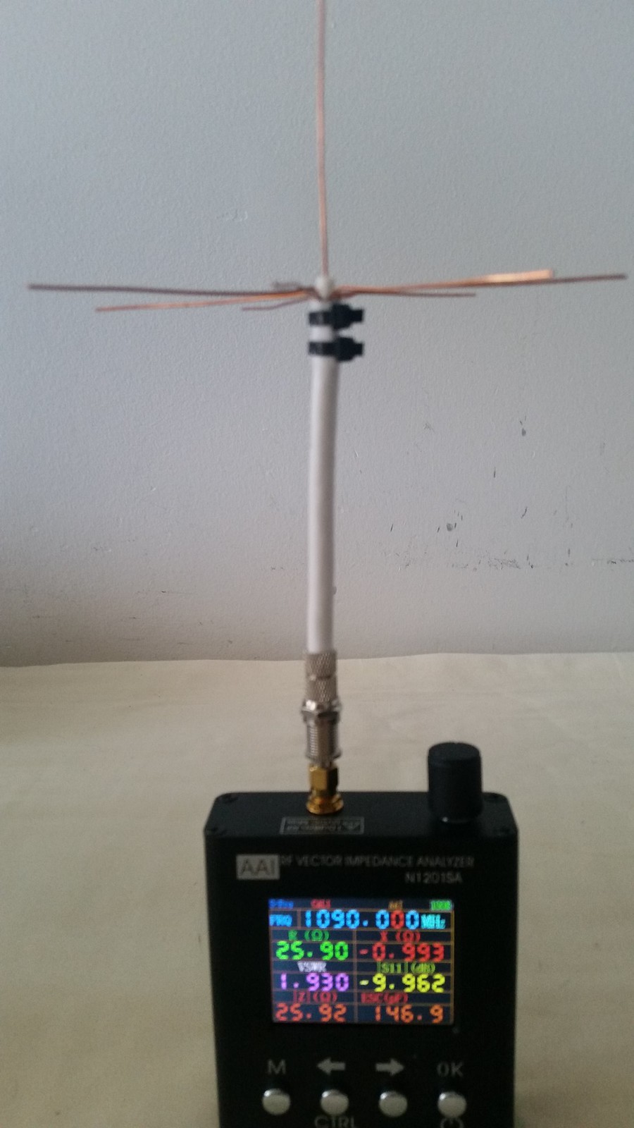
Horizontal radials, Impedance is 32 ohms
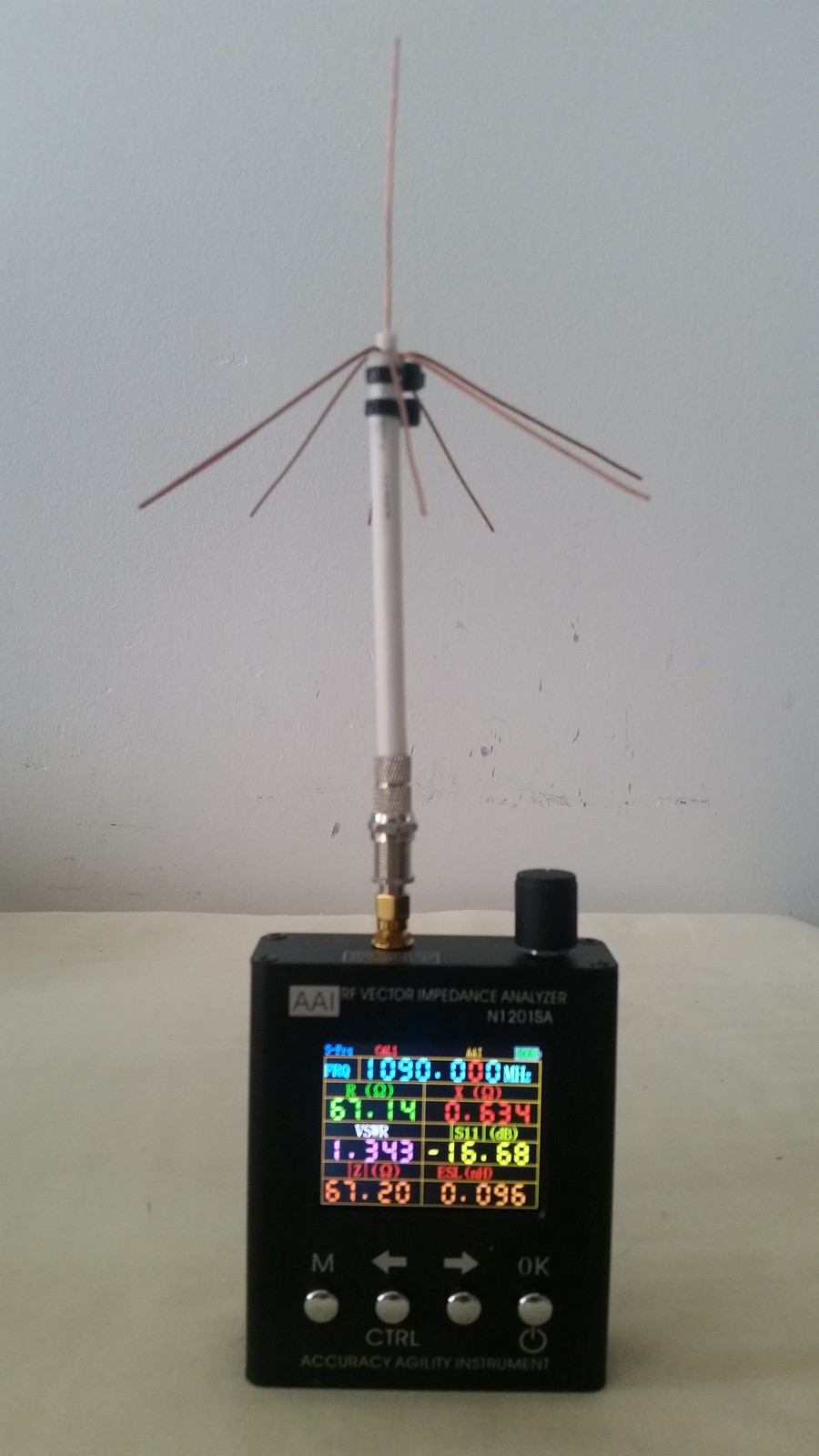
Slanting radials 45 degree, Impedance is 50 ohms
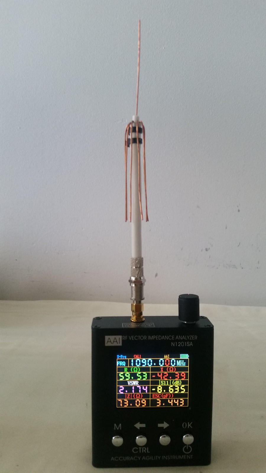
Vertical radials (=dipole), Impedance is 75 ohm
Thought I would share my results of the “QUICK SPIDER” vs. a cantenna. The only thing I changed was replacing the cantenna with the quick spider. The rest of the lineup (~40ft RG6 coax into a Nooelec2+ dongle into a Pi3 with a stock PiAware 3.5.3 install on Stretch). Happy to report that I am getting more planes and postitions reported, so this might be my next incremental change for my second site that has the blue FlightAware ProPus stick. Love seeing more of the planes and positions appear here in fly-over country.
A picture of the spider and cantenna (looking east) if any interest is below. The cantenna is 67mm across and 69mm tall (used to be a can of mushrooms ) The spider was built to abcd567’s specs in this discussion. Some might say the difference might be because the spider is 10 inches higher than the cantenna. Will think about that one… YOUR mileage may vary…
A brief update on my adventure with antennas and such. I substituted the FA ProPlus stick for the Nooelec2+ dongle, with the same spider antenna, same location, and saw a dramatic improvement in # of aircraft and positions. I suppose this is to be expected as I have a 300ft cell tower staring me in the face to the east, so the filtering helped plenty. Oddly enough, putting a FA filter in line withe the Nooelec2+ dongle made things worse
Next, I mounted the spider antenna up on my chimney, to make the reception horizon as unrestricted as I can with the trees and hills around me, FA ProStick Plus dongle. I think I am at the point of diminishing returns, happily - positions and aircraft consistently highest I have ever seen, and my range seems to very closely match my heywhatsthat prediction.
I’m pretty happy with being able to experiment with the no/low-cost antenna recommendations by many, especially the excellent write-ups and testing from @abcd567
I have gone from an average of ~200 planes/10K positions/day, to ~700 planes/90K positions/day and much further out since I started this fiddling.
Here’s a polar map after several days’ running with the new configuration.
For what it is worth, this is an update to my antenna experiments.
I applied for and was granted a FlightFeeder Orange kit. My goal was to compare the homemade kit (FlightAware Pro-Plus, home-terminated RG6 75 ohm cable, home-made spider antenna) with the FlightFeeder Orange kit (good profesionally-terminated 50 ohm cable, FlightAware antenna, FlightAware dongle, FlightAware filter). The FlightAware antenna is located on my (unused) chimney at the same elevation as the spider about 1 foot to the west and 1.5 feet to the north. The picture below is looking directly to the east. There’s a cell tower roughly 1 mile away, and the regional cable/communications provider’s central office for our town just below our home (the antenna/dish farm).
The cable lengths from the antennae are nearly the same and terminate to a Pi and the FA orange box in the basement. Both gains are currently set to ‘auto’.
I may have had unrealistic expectations that a professional kit would perform better than my home-made stuff. I have been surprised to find the home-made kit consistently gets me more plane and position counts farther out than the FlightFeeder Orange. Not by much, but enough to be significant in all directions during any observation period. So now my interest is renewed into finding WHY that is. I am not likely to move the FA antenna more east to the spider any time soon (aversion to climbing on rooftops). I stand on the shoulders of the folks who have tried different things and shared their experiences here (THANK YOU), and will start with gain adjustments on the Orange, keeping the Pi-Spider setup constant, to see what happens.
This is the sort of thing that keeps my interest in this hobby, especially when I happen to catch balloons from Project Loon floating by in the ‘vicinity’
P.S. The FlightFeeder kit that the FlightAware folks put together is top-notch, in my opinion - it’s about as painless and ‘plug-and-play’ as it can get - kudos for a job very well done.
Knowing what I known now, and taking into account where my RPi and antenna are installed - in the garage - the best bang for the buck is still an $8 no-name generic dongle, and a QuickSpider antenna.
Other installations and locales may benefit from pre-amps, filters, high gain antennas, etc., but not necessarily.
Very exciting stuff, abcd567! Thank you for the design, and others for getting me hyped to do it. The FlightAware newsletter recently (July 2018) called out your “Quick Spider” design, and got me excited to try it out. I’m very technical, (EE) but not used to building antennae, so I thought I’d add my experience for other noobs to ADS-B who were inspired by the newsletter, and who wish to do this:
Pros:
CHEAP - I mean, I literally built it with scrap Coax I had left over, two zip ties, and electrical tape.
Demonstrably better than the little NooElec telescoping antenna. I went from 40-90 messages/sec on DUMP1090’s page. (I’m guessing this is the best metric to use for comparison?) to 216/sec currently.
~15 Aircraft at a time to 35. (Mid-day, Tuesday, near KTPA) One of which I guess is AF1! (I kid, I know they don’t beacon ADS-B)
Max aircraft distance ~77nm to 118nm, and I just plugged it in 20 min ago. I expect to see even better.
I didn’t have the time or patience to measure perfectly, and the end result doesn’t look as good as abcd’s, and yet the performance is way better than “stock” - when it cools off in my attic, I may go back and trim, measuring with a digital caliper
Cons / Unexpected issues:
I was not prepared for the physicality of removing the insulation, braid, and plastic dielectric. It was a mess, and the braid is happy to stab you. Perhaps there is a much easier way, but I used a Klein wirecutter and wire stripper. It was a pain, and by far the most frustrating part. If you could source 18ga solid copper wire elsewhere, it would likely be a lot easier and you’d end up with more straight aerials and ground plane pieces. Any advice appreciated!
Inserting the ground-plane radials is not as easy as you might think. I jammed them in there with the aid of some pliers like abcd567 shows holding the end-result. some poked out of the plastic jacket when I was done putting in all 8. It still seems to work fine, I just wrapped the whole thing with electrical tape.
You will need an adaptor to your USB SDR (I have a NooElec one with the tiny little MCX connector.) I bought this on Amazon: https://www.amazon.com/gp/product/B072JCR57H/ref=oh_aui_detailpage_o00_s03?ie=UTF8&psc=1
The MCX connector takes a bit more force to push in than you might think, despite its tiny size. Be careful not to bend it when connecting, and push on the back of the ‘head’ of the 90 degree connector.
It is ludicrously hot in the attic in July in Florida! I’m going to work on this thing at night going forward
Thanks again for such a great post and design. I’m thrilled and will ruggedize this guy to go outsize on my old DTV mast later this week and report back. I am also interested to test it against the big dog FlightAware antenna I have on order.
Great example! Mine below isn’t near as pretty, but the tolerances must be pretty wide for this kind of design, because the performance is undeniable. Some stats from yesterday (Included crappy telescoping NooElec) to today (Quick Spider, same location, in my attic):
(for a full day/night cycle:)
Avg messages/sec: 58 >> 216
Avg aircraft seen: 12 > 35 (!!)
FR24 Max distance: 77nm >> 182nm (!!)
FA positions in the 100-150nm range: 3 >> 2,567 (!!!)
FA MLAT positions: 13,465 >> 48,312
FA 30-day moving rank: 7373 >> 7312 (in one day)
Needless to say, I’m thrilled! Wondering what I can do to tweak this Spider to be more accurate:
1 - Should I invest the time in straightening the aerials?
2 - Should I use the caliper to trim the aerials/ground planes to exactly 69mm? (I may be off 1-2mm right now)
3 - should I remove the weird metallic sheeting on the dielectric (i.e. just leave the plastic exposed for those 5mm)
4 - Should I put any effort into ensuring a better connection between the sheathing (braid) and the ground plane aerials? (I feel it was probably messed up badly when I shoved the aerials in the jacket)
5 - Should I put effort into ruggedizing this and putting it outside of my attic? (sealant, paint?)
Here are some build pics of my amateurish attempt:
Your radials appear to be nearly horizontal. If this impression is not due to angle with which photo was taken, then bend these down half way i.e. about 45 degrees. It does not need to be exactly 45 degrees. Few degrees (+) or (-) is ok.
The Spider is very tolerant to dimensional errors. One or two millimeter (+) or (-) will have little effect on its performance. Using accuracy of a vernier caliper is needless.
Cetrain must be a aircraft mechanic, engineer or a machinist f he is using calipers. I have several set. Then again,I am 30 year veteran aircraft mechanic.
Please see the post linked below. This post demonstrates the advantage of bending down the radials.
Bending down the radials to about 45 degrees brings the impedance of the aerial closer to system impedance (50+j0 Ω), therby improving impedance-matching and VSWR.


