Why are all Wireantennas differnt?!

Hello everyone,

my english is not the best so please excuse that…

i´m trying to recieve some ADS-B messages for a few day´s now and i know that my position is not the best at the moment but i can mount the reciver+ antenna on top of a 120m “tower” (windturbine…) but before i start bringing the stuff up that thing i try to build a “good” working" antenna.

Because of the very differnt results of the DIY Coax Collinears i thought i would stick to the “easyer” wire antennas… but every desing is totaly differnt?!
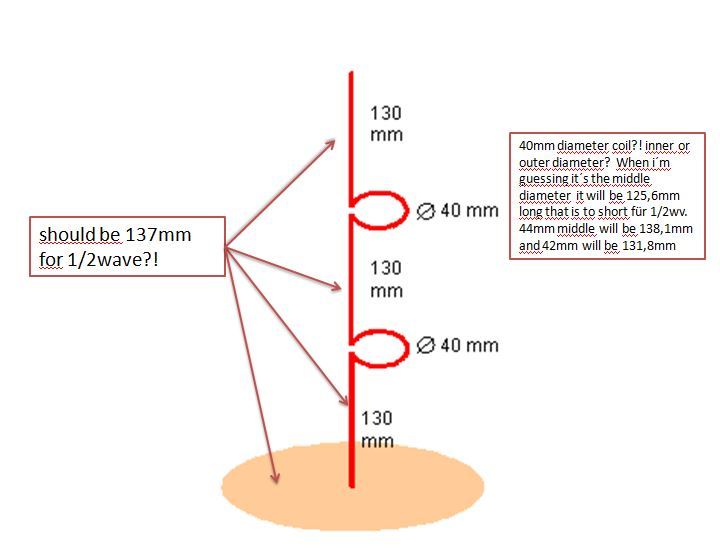
Design 1( Sprut/ abload.de/img/1z5rzj.jpg ) uses 1/2Wv Ground and 1/2Wv elements +1/2Wv coils…
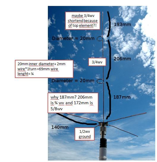
Design 2(G7RGQ/ abload.de/img/20ppbn.jpg ) uses 196mm Ground(?!?) 1/2Wv bottom only 1/4 wv Coils 3/4 top and middle
Design 3 ( abload.de/img/3ouqu3.jpg ) ist almost the same as G7RGQ´s but shorter Ground (1/2Wv) strange bottom at 187mm 1/4Wv coils…

all 3 are better performing than the 1/4Wv Gp and the stock/shortend stock antenna. But if i hook the RTL Dongle to roof gutter i will see some planes also…

My Question is why is everyone using a differnt type (lenght mostly) of the coil? From what i have found is that the coil is doing a phaseshift so that all parts of the antenna are delivering the right signal at the right moment (bad explanation i know…) but how can it be that someone uses 1/2 Wv for a coil and the next one is using only 1/4wv?

i´ve found some *pdf document ( abload.de/img/buchb1pb0.jpg ) from a german site and it states that a 1/2 Wv bottom element needs a transformer at the bottom because of the high impedance but with a 1/4Wv bottom this is not necessary( seems logic because of the well known 1/4Gp). After that 1/4Wv element you can add a phasing coil (how long should it be?!?) and another 1/2 Wv whip…

at the moment i´m trying a 1/4wv bottom +1/2wv coil+ 1/2wv whip and it seems that this thing is better than G7RGQ desing.

Honestly - these three antennas are probably far more complex than needed.

While the coils may help improve phasing and match impedance - the tolerances involved are very very very slim! Even a tiny error or variation in measurement is a huge difference with those designs at these frequencies.

At the height you’ll be placing the antenna, reception should be fantastic (assuming there is not RF interference from the workings of the windmill!)

Unless you’re very experienced with microwave antenna construction, I would stick to a groundplane spider, or “cantenna”

From this thread: ads-b-flight-tracking-f21/three-easy-diy-antennas-for-beginners-t20177.html

Cantenna


Spider

With the cantenna mounted inside my window, I was getting range of 120nm consistently.

Currently I have the FA antenna mounted on a pole basically at the roofline of my apartment outdoors, and the range is indeed better.
FlightAware sells a decent colinear outdoor antenna for $40 - for your application, if you can spare the cash, I think it may well be worth the cost simply for the weatherproof nature of the antenna.

If you can’t afford it, cant get it delivered to your location, or are simply adamant about building your own antenna, I suggest “cantenna in a jar”
http://forum.planefinder.net/attachments/dsc03294-rr-jpg.483/

I would definitely install a bandpass on your setup for two important reasons:

  1. The generator and switchgear inside the windmill definitely create near-field RF interference. The farther you can get your antenna away from them, the better.
  2. There is probably already an antenna on top of the windmill for remote control and monitoring, and from what I can tell these are usually cellular datalinks that will run on frequencies near ADS-B (GSM 900mhz seems common) unless filtered, this will have a serious impact on performance - and even with the filter, you’ll want your antenna as far away from the existing antenna as possible, (while also being as far away from the switchgear as possible. Might have to find a happy medium there)

Lastly, and this can’t be helped, you’ll have “RF Chop” on signals when the blades are spinning between your reciever and the aircraft, but this will only affect a part of the sky view, and probably won’t impact reception that badly.

Snap some photos when you get your setup going up there, if you can! very curious to see

best of luck.

@Stummel

The question you have asked about the “wire length in coil” is very difficult and nearly impossible to answer :cry:

The answer to the question “why so many designs” is that none of these is a properly engineered design, and every one who has posted his design has just made an aproximation, and none of these give good performance (gain, swr, radiation pattern) as claimed by their makers. These are all “Piece of Art”, rather than an engineering masterpiece.

All the antennas you have mentioned in your post are COLLINEARS made of wire.
**All COLLINEARS are very easy to make, but very difficult to get right. **

Making a COILLINEAR antenna without proper test equipment and technical know how is a “Dark Art”.

Length of wire, number of turns, diameter & length of coil affect phasing. If you dont have proper test equipment, the only way to find out correct parameters of coil is “trial & error”.

Hello,

Percise manufacuring shouln’d a problem… its just one piece whit a few dimensons,no assembly like a coax collinear

If there were only small differences between the coils i could understand it but the difference between 1/4 and 1/2 a wavelenght is hughe and it should be possible to calculate a teoretical good design and do the rest with try and error/simulation…

So far my 1/4 + 1/2coil +1/2 whip is as good as g7rgq’s design

Try 1/4 + 1/2 Stub + 1/2 Whip (Franklin Spider)

  1. With 45 degree slanting radials as in photo below.
  2. With horizontal radials.

Theoretically horizontal radials with this collinear (Franklin Spider) should give better performance than 45 degrees bent down radials. Testing both will show practically which one is better.

Designed & drawn by abcd567

Based on abcd567’s design, the prototype built & tested by Planefinder member Xforce30164

1 Like

BTW I should mention the cantenna I posted is ABCD’s design and he’s pretty much the authority on antenna engineering around here insofar that I’ve seen.

Though - and not to throw rocks at giants - wouldn’t that franklin spider antenna work considerably better on an N-type connector than SO-239? As I understood it SO-239 performs poorly above 100-300mhz and has high forward reflection and insertion loss.

qsl.net/vk3jeg/pl259tst.html

@JonHanford:
Thanks for highlihting SO239 vs N connectors.

The use of SO239 in above design & prototype is not because it is best and most suitable connector, but because of it’s popularity.

This does no mean that other better connectors cannot be used. N connector can definitely be used instead of SO239, as it performs better than SO239 at Ghz frequencies.

Hello,

Antenna 1 (1/4+1/2coil+1/2) is as good as g7rgq’s design after 24h of testing and it seems that the one with the shorter 1/4wv coil isn t that good…

My Antenna 1 is much like your Franklin Antenna dimension wise…

I’m using a Aluminium Mesh as ground and can change only the radiating wire…

Does anyone know which difference 1/4wv and 1/2wv radials make?! 45° bending should be done everytime because of the impedace i guess?!?

Yes, the angle should be 45 degrees ONLY if (a) the whip is 1/4 AND (b) system impedance is 50 ohms.

I have today carried out simulations for different angles and different lengths of radials for Franklin Spider for use with 75 ohm system.

Simulation results show that the Franklin Spider with horizontal radials having length 1/8 wl (34 mm) is best for both Gain & SWR @75 ohm. Please see simulation # 3 in the image below.

**Please note that simulation results can only be considered authentic if proved by making a prototype and putting it on trial run. **

I plan to make one prototype like xforce has made.
(1) Run it for some time, and record performance.
(2) Bend the radials up, to make these horizontal, and again run it for some time, and record performance.
(3) Start cutting the radials in steps of 10mm till reach 40mm, and record performance after each cut.

(4) Compare all results to find out which one gave best result.