
Since 1090 is line of site communications its best to have the antenna in the clear and high as possible. Mine is about 15 feet above my roof line. I understand many folks cant have the same setup. But I suggest is to get the Antenna as far away from any computer or RF noise sources as you can.
1 Like
I did some more experimenting on locations for the Pi, Prostick and Antenna. I didn’t have a can that would stay on the window mullion (too narrow), but I had a few washers about the same diameter as the base of the antenna. I taped them at a few locations on the transom and mullion, and tried the antenna in different places. Again, the middle of the window seemed to be a little worse than near the edge so I settled on where it is shown in the photo below. Reception was about 100 messages/sec.
The eureka moment happened when I taped the antenna cord to the vertical frame; reception jumped up to over 300 messages/sec., and I am seeing some planes out to almost 140NM! Not sure why fastening the cord has done this…
Going to pick up a metal plate of some kind (maybe a blank plate for a electrical box) and double side it to the mullion to see if there is any improvement.


On my previous location i was living in a house with developed attic.
I did lot of excecise where in that large room to place the antenna.
And i have identified that the best position was in the middle of the room, away from walls and window frames. The closer i get to any of this, the recption dropped in that direction.
The roof itsel did obviously not have that much impact.
So putting the antenna more or less close to a metal window frame might not be the best idea if there are other locations available.
That points to an intermittent electrical connection.
I’d say the antenna itself or the coax is defective.
Really for reliable reception you want a proper antenna and not one of those whip antennas they are not very good quality.
Of course the usual outdoor antennas are a bit bigger and won’t look as unconspicuous in the window.
The shield is NOT soldered to base plate, just a pressed contact. Bad assembly or little pull may result in hidden broken contact. Even the core may have a dry-solder with the whip. See last photo what happened to one of my magmount whip.


1 Like
That points to an intermittent electrical connection.
I’d say the antenna itself or the coax is defective.
That’s very possible; it was about $4 from Amazon…
Really for reliable reception you want a proper antenna and not one of those whip antennas they are not very good quality.
I will try to build one in the future. A coax collinear of some kind.
Added a little more tape to secure the wire, and a plate under the antenna. Left it in the corner for now since I can hide the Pi/Receiver. Hitting about 450 messages per second, out to around 140NM. Huge improvement; thank you all for the suggestions.


5 Likes
Very good results with a mag-mount antenna.
If you have a thin tie wire or one of the wires from scrap network cable, just make the whip shown in photo below, unscrew the regular whip and use your DIY whip.
No harm in trying. If DIY whip does not prove good, just throw it in trash and re-screw the regular whip.
As I live in an apartment in a high rise building in an urban area with lot of RF noise (Cell phones, FM, TV etc), I needed to add a filter to get good results with this antenna. You may or may not need a filter.
CLICK ON IMAGE TO SEE LARGER SIZE

3 Likes
Now “me want cookie,” too! I totally missed the function of the “can” in cantenna. Attach a can cover to my magnetic antenna base, and I see an instant message boost:


To control for traffic variation, here is from my other setup using the FA brown rod.

Clearly, there was no meaningful traffic surge. In fact, the shorter antenna had underperformed the long rod for many weeks since the former setup suffered a noise increase that I haven’t figured out. With cookie can, it now consistently beat the rod again.
(Update below) What is surprising is that this is not due to a reduction of noise base even though I saw a reduction in ADS-B CPU usage which is normally associated with noise reduction. Noise fluctuation for the period isn’t very different from control, nor significant enough to have the amount of effect on CPU.


On control,


Update: The effect does come from noise base reduction. Turns out that busy travel hours are not good for noise estimation. During the night, my Pi setup now returned to previously “good” levels. My guess is that some sort of physical alignment in previous times made noise low by accident but any disturbance could elevate noise. Now it is more consistent.
Think of the way a mag base antenna works:
The coax shield doesn’t have electrical continuity with the metal base it’s sitting on, but rather it is capacitively coupled.
Probably what you have done is substantially increased the coupling when you taped the cable to the metal frame.
What you have really proved is that these mag-base antennas are third rate. On the plus side, you seem to like experimenting, so you’ll have a lot of fun optimising your site.
1 Like
Check the DIY antennas provided by @abcd567
I made a very easy one after i bought the whip by exchanging it with a DIY one made froma piece of TV cable. Improvement by 30%
1 Like
1 Like
Going to give this a shot ASAP. I have some steel wire, and could pull some copper from the core of some coax to experiment a bit.
The more I read, I want to try a collinear. Do you cut the segments long to account for the overlap when they are striped and inserted/soldered, or just cut the segments at the length that is 1/4 or 1/2 lambda?
1 Like
Whichever wire you use, better it be thin, as winding few turns over brass stud of base is difficult with a thick wire. Please see photo below.
Most TV/Satellite coax have a core wire made of copper-coated steel. It looks like copper wire, but is very hard compared to copper wire. I have once broken the brass stud of magmount’s base trying to wind the coax’s copper coated steel core wire over it.
You can check if the core of coax is copper or copper-covered steel by a magnet. If core wire clings to magnet, it is steel, if it does not, it is copper.
Better use one of the several core wires of a scrap network cable, as it is thin and made of copper.

Cut the segments long enough to account for the overlap when they are striped and inserted, as shown below

For 1090 MHz, Wavelength (lambda) = 275 mm
L=0.5 x 275mm x Velocity Factor of Coax
If Velocity Factor of Coax is 0.85
L=0.5 x 275mm x 0.85=116 mm
If Velocity Factor of Coax is 0.66
L=0.5 x 275mm x 0.85= 91 mm
You must use correct Velocity Factor of coax. Using inaccurate Velocity factor will result in a poor performing antenna.
The VF varies with manufacturer and model of coax. Use Velocity Factor from Spes / data sheet of manufacturer of coax you will use for making the Coaxial Collinear antenna.
Yepp, this was it. I still have it in my “all mens” box of cables
With respect, you are trying to polish a turd.
You’ve demonstrated the base is … temperamental at best.
Play with it by all means, but keep in mind it’ll never be a ‘good’ antenna.
As for the colinear, many have been built and only a few perform well, so be prepared to scrap a few builds and retry if it doesn’t perform.
Buying ‘bargain cable’ is a sure way you’ll never get it to work, because it’s almost impossible to work out the the correct cable spec’s.
Totally agree with you: the little antenna and base are a POS, and building a collinear will be a trial and error, with failures before successes. I enjoy the tinkering though; it is fun to make something out of very little and I been given some good ideas and direction on here. I am curious if the base cord is bad, or if taping it to an aluminum window frame did some noise cancelling?? More experimenting…
I will look for some quality cable for the CoCo (solid advice); copper core and braid, and probably make more than a few mistakes… do I need a tube Balun or ferrite bead choke? Or both? I will try.
Some good numbers over the last couple of days from the suggestions in the group (trim antenna, metal plate, antenna position…). Thank you all.

1 Like
Taping the coax to aluminum of window resulted in grounding of coax shield through the capacitance formed between the coax shield and the aluminum of window.
2 Likes
In furtherance of the experiment, I grabbed a PCB antenna and a couple of 6’ lengths of RG-58 from Amazon for about $15, and it seems to work significantly better… as expected? I used a very professional painters tape mount to the window… the connector on the antenna is not a bulkhead type with the long threads; I will find some kind of small bracket and use double sided tape.
Started to get some planes in the 200-250NM range for the first time!

4 Likes
The PCB antenna has really increased the range of hits that I am getting; some over 250NM.
There does seem to be a problem with the rate that messages are collected however. Sometimes I am over 500 m/s, then if the dongle is moved slightly, it drops to less than 100 m/s. There is no change to the position of the antenna, and touching, moving or rotating the dongle seems to be the only change hat causes this effect. Also, the dongle (Prostick Plus dated 2017) seems to be really warm most of the time, but I have read that is somewhat normal.
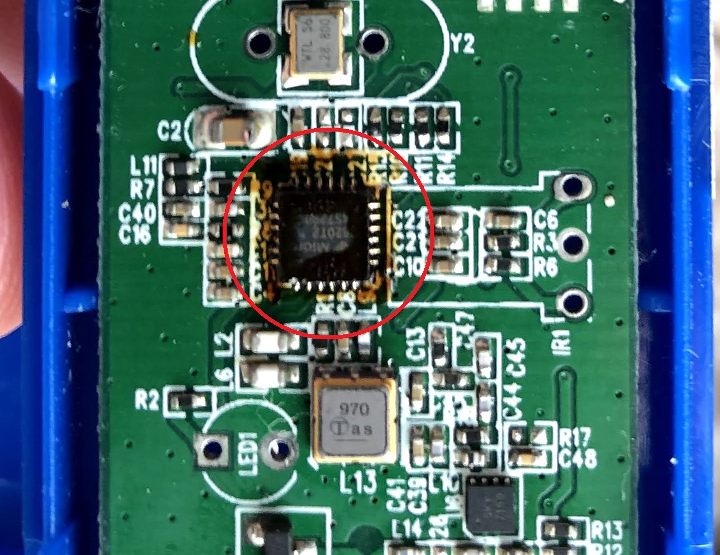
I opened the case to see if perhaps there was a loose connection at the SMA connector, but it all looks OK. There is some discoloration on the circuit board that maybe looks a little burnt (red circle). Could this be causing the inconsistency in the rate that I am receiving messages?

1 Like
The only sure way to find out is to try another Pro Plus, if you have another one.