After having installed my new Uputronics Filtered Preamp, I noticed the noise level on my stats page jump up. This triggered me to look in to optimising my gain settings, which I’ve been trying to do over the past couple of days but without much luck.
Part of the problem I’m having is figuring out what level of noise is acceptable. Prior to installing the preamp, noise was around -30dBFS, which jumped to around -20dBFS when the preamp was installed. This is to be expected - but is that acceptable? What effect is the filter having - is the noise level acceptable because there’s a good filter in place, or is any noise bad?
I reduced my gain down to 22.9db which bought my noise level to around -30dBFS again, but then I worried that I was just negating the amplification from the preamp. Bringing the gain back up to 43.9db increases the number of messages >3dBFS and also increases the noise, but does this mean I’m going to see more traffic from further away? I’m situated underneath the flight path for a large international airport (although aircraft are usually between 15,000-20,000ft above my house), but am also very close to two smaller airports with a lot of GA activity during the day which can be anywhere from 500-1000ft.
In short - I have no idea what I’m doing and am trying to make sense of this all, so any information anyone can provide would be extremely helpful! I’ve attached a screenshot of my signal level stats if it’s any use - the blip at the end is me increasing the gain from 22.9 to 43.9.
In terms of equipment… 3.3dbi ADS-B Antenna → Uputronics ADS-B Filtered Preamp → FA ProStick+. It’s all currently situated in my loft.
@phoenix125
Below is image you posted, but it shows as a link. Why? A missing exclaimation mark ! at start of img code.
Correct format; 
I gave up trying to optimise numbers as at my location almost all the traffic is radially in and out and very little flying by.
I have two independent Pi systems and optimise one by comparing it to the other which is kept unchanged as a reference.
I look at three parameter; Aircraft Seen, Position report count and Maximum usable range. If the Maximum range goes up the number of aircraft goes up.
Over the last few days I have been decreasing gain on one system from -10 to 30dB and not found a change in aircraft seen compared to my reference.
Another Site about 2 miles from me consistently sees about 2% more aircraft and about 50% more position reports so I still have more work to do but the next step appears to require a higher and possibly better antenna and then both my signals and noises will go up and I’ll have to start again.
I am trying to maximise my range to pick up the tangential flight paths in the red ovals.
Everything else is travelling radially and I can detect and count the plane at some part of its flight regardless of the antenna, amplifier, filter or gain.
All I was trying to say, somewhat clumsily, is we are both trying to maximise plane count but we have quite different obstacles to overcome and hence different methodologies.
I am contemplating using a high gain directional antenna pointing at the planes I should be getting but currently missing. This will increase the signal strength from the target planes and hopefully further decrease noise from sources from other directions and at least then I’ll know if they should be observable from my current location.
I’m getting lazy in my old age so I will probably just order one of these off ebay and if it doesn’t have enough bandwidth to get to 1090 with usefull gain it wont take much to tweak it up.
With the existing boom and feed it will be easy toshorten element length, including the driven element, and adjust position. Certainly a lot easier than starting from scratch and the current feeder already has a type-N.
A Man’s Got To Have A Hobby: Long Summers With My Dad by William McInnes.
The price looks good but the specs, not so much. “frequency range between 824 MHzand 960MHz” is a mile away from 1090. Changing the element spacing will be your biggest problem. Good luck and report back on your success or failure.
You might need a little more filtering. If you have a spare Flight Aware filter laying around, put it on the Ant side of the Uputronics and see if it helps. I made a difference in messages per second and range in my location, two miles away from a bunch of antenna towers.
The frequency does seem a long way away but they are quite large diameter elements so there is a possibility that there may still be some useful gain at 1090.
It not, the hardest part will be resizing the folded dipole driven element but it shouldn’t be two hard to cut it and trim the length and then find some way to sleeve it and screw it together. Worse case is I’ll just make a new driven element out of bent coat hanger wire. I’m relying on the balun or other feed device not requiring rework.
I’m hoping the parasitic element spacing will be OK and they just need a trim. Time will tell.
It will take a month or so to get here so I have plenty of thinking time left.
I actually replaced the FA filter with the Uputronics, but i could definitely put it in and see if it makes a difference. I do seem to be getting more messages at gains around 40.2db, but then my % of messages >3dBFS jumps up to around 22%. The high rate of messages >3dBFS doesn’t seem to be affecting message reception though so i guess for my setup that would be acceptable?
In terms of the overall setup, I was thinking of purchasing the FA antenna as well. I’m guessing that gain at the antenna is preferable as it will be in the specific range required, whereas gain at the tuner is over the entire spectrum?
NOTE: During conversion from forum’s old BB Code format to current Discourse format last year:
The images in above post got changed to links .
Editing of old posts is NOT allowed, so I am unable to correct this discrepancy in original post.
I am re-posting here the post linked above because of above reason.
.
.
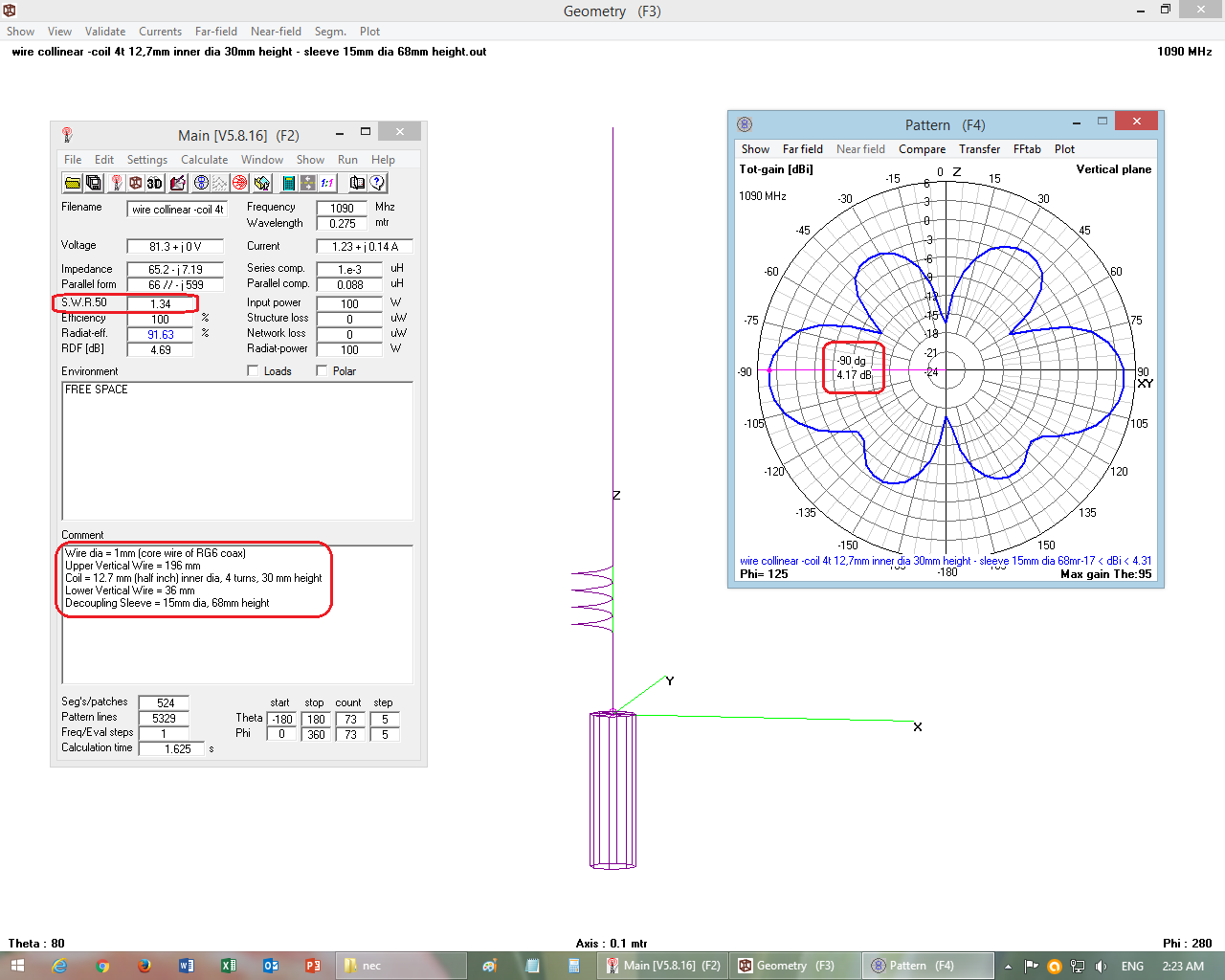
Off Designed-Frequency Behavior of 2 Types of Antennas
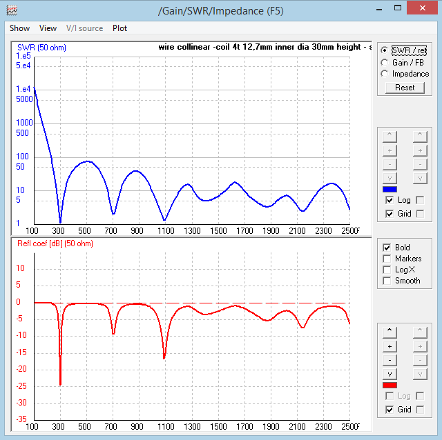
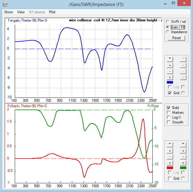
Frequency Sweep (From 100 MHz to 2500 MHz) of Wire Collinear Antenna and 1/4 Wavelength Ground Plane Antenna.
The frequency sweep results of a high gain wire collinear antenna show that it not only performs best at its designed frequency, but also performs fairly good at or near sub-multiples and multiple frequencies.
This characteristic of collinears is good for multi-band reception such as single antenna used by Armature Radio Hobbyists for 2 meter band and 6 meter bands. However it has disadvantage for single frequency reception that the RF signals picked from all these multiple & sub-multiple bands necessitates a tuner circuit or a filter at front end (i.e. between antenna and receiver).
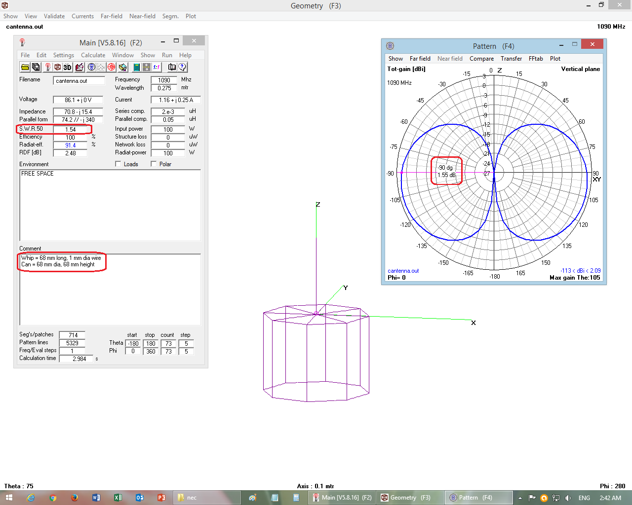
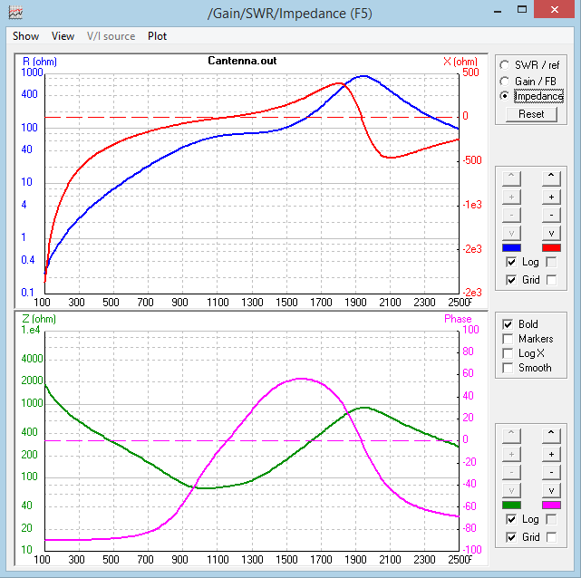
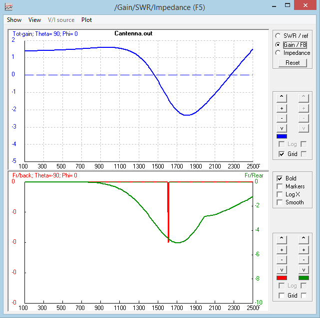
The frequency sweep results of a 1/4 wavelength ground plane antenna show that it gives good performance at and near its designed frequency only, and at other far away frequencies its performance is poor. Hence the 1/4 wavelength ground plane antenna picks very little harmonic and sub-harmonic frequency signals.
WIRE COLLINEAR ANTENNA WITH DECOUPLING SLEEVE Click on the thumbnails to see full size images
. . .
.
.
.
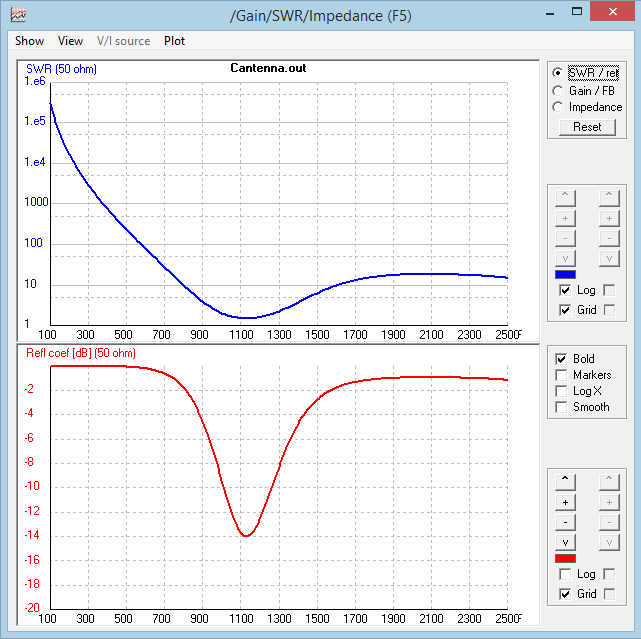
1/4 WAVELENGTH GROUND PLANE ANTENNA (Cantenna) Click on the thumbnails to see full size images
Did another frequency scan this morning and got pretty much what I expected - this is with both the FA filter and the Uputronics Filtered Preamp in place. So it looks like I’ve got enough filtering in place (apart from that ridiculously strong signal at around 923mhz… no idea what that is).
I’m really struggling to find a good gain setting, and today I’m getting completely different results than I did yesterday. Seems there are a number of variables in play… the weather is more overcast today, the loft is about 5-7 degrees cooler, so that could be playing a part in it.
It seems like I have a couple of options:
High gain - around 43db - maximum messages and position reports, but high noise floor around -15dBFS so less range and more intermittent tracking of individual aircraft
Low gain - around 25db - least amount of messages and position reports, but low noise floor around -30dBFS so higher range and continuous tracking of individual aircraft
I observed something yesterday that I’m still investigating. With a lower gain value, I was using 20.7, the noise level varied a lot during a 24 hour period. That may affect performance in a negative way.
I then increased it to 36.4, that seems to be my maximum before saturation and ‘diminishing returns’, and the noise level stays pretty flat at around -20. Performance seems to be more consistent, and good.