
I use spare 12 or 14 ga Romex, strip a bit of the end going into the connector, and cut it to length leaving the insulation for visibility. I need all the help I can get ![]()
Just wondering: Would leaving the insulation on affect the velocity factor and thus optimal length? I would think so but never measured.
/paul
VF depends on the material through which the electromagnetic signal passes.
In the case of Coax, the electromagnetic field, due to rf signal travelling along the cable, is totally confined within the space between core & shield. This space is filled with core insulation. Hence VF of the core insulation applies.
In case of whip wire with insulation, but no shield, the electromagnetic field exists in the space between core and the transmitting antenna of aircraft. Hence the material through which the signal from an aircraft at a distance of 100 km passes, is composed of 100,000,000 mm of air + 4 mm of core insulation. This makes medium of propagation 99.999996% air and 0.0000004% core insulation, which, for all practical purposes, is same as air, hence VF=1
Edit: Removed formulas to make description easy to understand.
Makes perfectly sense to round that! Thanks for clearing!
/paul
I’m fairly new to this myself and have been online for less than a month. My first few days were with the “stock” antennas that came with my “noo” dongles. (have both the R820T and R820T2) Since I had a bunch of RG6 laying around, my first attempt at building an antenna was a COCO based on the dimensions here balarad.net/ . My range results without amplification are below. (50nm rings)
Cheers!
LitterBug

Great! Conratulations on being amongst few lucky ones who get good results from their first DIY CoCo.
150nm to 200nm max without amplifier is very good.
What is:
(1) Antenna location (indoor or outdoor).
(1) Height of antenna.
(3) Length of coax between antenna & receiver.
- outdoors on roof. Not as High as it should be but that will change when the ice/snow are gone.
- Currently about 15 feet above ground. partially blocked to north by roof and west by neighbor’s house.
- I’m going to have to guess about 40 feet of coax to the receiver with a ground block before entry.
Would really like to put it on my Dad’s 60 foot ham tower on other side of town. ![]()
Cheers!
LitterBug
PS: 8 segment, unterminated, encased in pvc. All RG6 quad shield 3.0 Ghz rated cable. (will find exact specs one of these days)
**@karllitterer: **
Thanks for details. Seems you made a good CoCo, which gives 150 to 200 nm with 40 feet coax, and no amplifier!
Great. Now add an amplifier, and your max range will increase by 50nm to 100nm over your current max range.
Thanks for the feedback. I have an amp or two to try out. Just waiting on the big warmup next week to get up on the roof. ![]() Looks like spring is just around the corner. At that point I will get some pictures and throw down more details of the complete build.
Looks like spring is just around the corner. At that point I will get some pictures and throw down more details of the complete build.
Cheers!
Litterbug
[quote=“karllitterer”]
Well, being the impatient, OCD person I am, some of my checking and testing has begun before jumping up on the roof next week.
Cable
A) My Coax is Coleman Cable (CCI) 92041 with a VF of .81
B) Based on that, my COCO is in theory tuned to 1043 mhz with the 116mm segments
C) I will be building another “1090 optimized” with 111mm segments for comparison
D) If shorter is indeed better, the 116mm segments on my current COCO will be shortened and I can either test a 16 segment config, or set up a second feed on the other side of town. (on a 60 foot ham tower would be nice!)
Amplification
A) I played with a handfull of amps with a 1 Meter lead in front of my RTL-SDR
B) The Motorola BDA-S1 (52-1003mhz) appeared to have an immediate gain compared to the others.
C) My overall range did not change, but the tracked and reported jumped 20-30% and more/most last seen numbers are <2
D) this amp has options for local and remote power and is weather sealed.
E) The Motorola BDA-S1 will be going up to the COCO when the weather breaks.
Other
Planning on doing a Spectrum scan/comparison between this and other antenna feeds I currently have.
My OTA HDTV feed provided positively 0 detection but pulls in TV great. LOL
Cheers!
LitterBug
I’d try shorter less than 16 segments (easy to do before the coco is encased) - just to find what works best … it could easily be a case of less is more.
Did not have much luck with homebrew coco on 1st go.
Much better results from simple to make wire 6 element Franklin co linear thanks to abcd567 for the design via another forum.
Regards,
Mike.
MY NEW DESIGN:
HYBRID OF FRANKLIN & SPIDER
**FRANKLIN SPIDER
Gain = 4.14 dBi
SWR = 2.09

SPIDER
Gain = 2.08 dBi
SWR = 1.97

Important: Total length of wire in phasing stub = ½ wavelength = 138 mm.
In above simulation, stub wire total length = 66mm+6mm+66mm=138mm
Stub gap (center-to-center distance between horizontal wires of stub) is NOT critical. Can be 6mm +/- 1 or 2 mm.
Based on my above design, an antenna was built by forum member xforce30164, and is on trial run:
http://forum.planefinder.net/threads/ads-b-diy-antenna.23/page-131
**

Yes!
A simple design - much simpler to get right than a coco … and it has the possibility it could be sneaked onto a roof (or up a tree) where the residents committee / landlord says “no antennas”.
Let them say no to me… Whip out the OTARD and the problem goes away.
EASY SPIDER, MADE OF COAX-ONLY.
No SO239 or PL259 or N-Connectors required.
No Soldering Required.
TRIAL RUN

IN 5 STEPS
Step #1

Step #2

Step #3

Step #4

Step #5

Lowl, above antenna could be me from desisgn.
http://pd0rtl.blogspot.nl/2014/07/3th-version-ads-b-antenna-satcable.html
direct driven sat cable GP.
cheap, and with in 20 minutes to make (if all items in house) (well, i just made a 2nd 1 for testing with the airspy…)
260 KM farest plane atm.
Something to note for non “hams” making a CoCo antenna. Not all wire is the same and therefor the 1/4 wave elements need to be sized differently depending on the brand of coax used. My first one I used the velocity factor of .83 and I only got out about 100 - 150 miles (I am 25 feet up). Not good. Later I Goggled the brand of wire I had and its factor was .78. the difference is 114 to 107 mm in length. I cut my new elements to the shorter length and I am now picking up over 250 miles. No amplifier. Another thing is making your cuts. They need to be square to the axis of the wire. I am using RG6 from Home Depot. I cut about 3 inches too long. Straighten the wire piece and “roll” a razor blade over it to cut through the outer sheath, foil, and braid. Try to just nick the inner insulator. Twist and pull. Nice clean cut with no frays. Now measure and cut your second side. Easy this way to be accurate to less than a MM. The gain on these antennas is produce by the summing of the signal picked up by each little piece. If the segments are not the same length, you will not have good results. A short or long element can even subtract from otherwise good gain. I have 8 elements. If you assemble them in pairs, you can check from center to center conductor for shorts. Then assemble the pairs and test again. Never have to mess with the outer braid this way. I use a piece of tape between the elements to prevent shorting, then use heat shrink to join. Since the braid is aluminum on my wire, to terminate the “ground” I pushed a piece of wire up inside the braid about 2 inches. Now there are two stubs you can solder to. My dongle, piaware, and hub are mounted inside a piece of 3 inch pvc pipe. I wifi back down to the base computer so as not to have any long runs of coax. I will be glad to make these antenna blanks or even systems for anyone if there is interest.
SIX LEG SPIDER
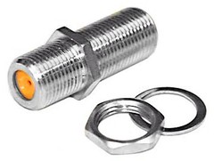
**USES ONLY F-TYPE BARREL CONNECTOR (With Nut & Washer)
https://farm8.staticflickr.com/7607/16586196409_0eec8220c9_m.jpg**
NO SOLDERING REQUIRED
NO SO-239, BNC or N CONNECTOR REQUIRED.
FINISHED LENGTHS
WHIP: From top of F-connector to top of whip = 69 mm
RADIALS: From Point of bending down to tip of radial = 69 mm
RADIALS BENDING DOWN ANGLE: About 45 degrees below horizontal
WIRE DIA: Flexible. In this demo core wire of RG6 coax cable is used which has a dia of 1 mm (18 AWG), but wires with bigger dia can as well be used.
STEP-1

STEP-2

STEP-3

ON TRIAL RUN

DIRECTLY BUILT ON AN AMPLIFIER, INSTEAD OF F-BARREL CONNECTOR


