
Those numbers don’t make any sense without more information. dB are a comparative measure, so unless you know what the comparison is, they don’t tell you anything - larger numbers could be better or worse.
Do some research on the cable before buying it. You want a cable that you can find the manufacturer’s spec sheet for that indicates the “Velocity Factor”. Having that information will allow you to dial in the optimal segment length without having to do a bunch of trial and error. Personally, I have been using CCI 92041 RG6-Quad Shield with great success. This cable has a 81% velocity factor. Based on my testing, the ideal length of 112.4mm holds true.
Cheers!
LitterBug
I didn’t bother with any of that 8) I had a few dozen metres of satellite cable in the garage just labelled SAT100 so probably something generic.
I started with a 6 segment one with each segment about 112mm. Open top, no baluns and put it on test in the loft. I got some idea of the range I was getting, took it down, chopped a couple of mms off and started again. Keep going until you find the “best” for your location. My element lenght was 91mm so it took a while. It looks like my cable had a Velocity Factor of 0.6. Most coax has Velocity factor of around 0.82 unless you choose to buy something exotic.
Blue ring is maximum distance calculated by Heywhatsthat.com at 40,000 feet, the red ring is 30,000 feet and the green ring is about 1 weeks worth of gathering data. I don’t think there is much more I can do – or is there ![]()
I’ll post some pics of my attempt at making a coco with copper tube & putting the inner + insulation inside it. I’m hoping it will be a bit more robust than just pushing the core between the outer and braid.
I lost my whole antenna a couple of weeks ago when it snapped at the bracket during some big winds. The antenna does tend to swing around a lot in a gentle breeze. The above is a 12/14/16 element one as I’m not sure how many of the segments came apart when it fell. I didn’t bother to check, just put it back up again.
So the screening attenuation does not have any influence at all? Its only all about the velocity in terms of the length of each element?
I have never seen a coax with such a high dB figures like 65dB, 90dB or 120dB. Such high dB figures are specified with Amplifiers.
The only dB figure specified with coax is Attenuation in dB/100 meter or dB/100 feet.
For most RG6 75Ω cables, the attenuation at 1000 MHz is typically around 6.5 dB/100 feet or 21 dB/100 meters.
The Velocity Factor is typically around 83% for FPE (Foamed Polyethylene) insulation.
For the purpose of making a Coco, attenuation is unimportant as Coco’s length is less than 2 metes (6 feet), and hence attenuation is less than 0.42 dB (2 meter x 21 dB/100 meter), which is negligible.
right, Velocity Factor is almost the same, but attenuation varies more: (from 20dB/100m up to 40dB/100m), I assume the lower the better. Right?
produktinfo.conrad.com/daten … _de_en.pdf
produktinfo.conrad.com/daten … U_TERR.pdf
produktinfo.conrad.com/daten … 75_OHM.pdf
What about shielding? single, double, triple? Doesnt higher shielding make it harder for the ADS-B signal to get to the receiver?
Attenuation is not so important for the co-co itself, because attenuation is proportional to distance and the co-co isn’t very long. Lower attenuation is better, obviously, but probably your feedline is much longer than the antenna itself so worry about that more!
In a co-co you are using the coaxial sheath as one of the receiving elements anyway, it’s not shielding.
I fully agree.
In a co-co you are using the coaxial sheath as one of the receiving elements anyway, it’s not shielding.
This is partly correct.
The shield performs both the receiving as well as shielding functions.
The OUTER SURFACE of shield receives the RF signal when Radio wave from aeroplanes strikes it, but remaining thickness of the shield prevents the Radio waves to penetrate it and reach the core wire.
The core wire acts as phasing element, and to perform optimally, it should not intercept any Radio wave arriving from the aeroplanes.
Most dual shielded (1 foil+ 1 braid) coax have about 95% shielding and allow less than 5% RF signal to reach the core, hence perform well.
This is the most commonly used coax for Satellite/DBS and also used for coco making, and generally gives good performance both as coco & medium length TV/Dish cable.
The quad-shielded (2 foils + 2 braids) coax has shielding higher than 95%, and is used for transmission of RF signal where RF noise is high.
This is costlier compared to dual shield. If used in coco, it will somewhat improve the performance of coco, but not much.

EVOLUTION OF A COCO / HOW A COCO WORKS
WIDE IMAGE - Scroll Right to see in full

Some details of the direction we are taking for our new coaxial collinear installs and retrofits when needed.
We like coaxial collinears because they are cheap, easy to build, can have lots of gain, and can be protected in a sturdy radome.
Our goal, whenever possible, is to avoid the need to insert extra amplification and power inserters in the system so we work to maximize gain from the antenna.
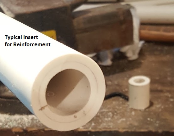
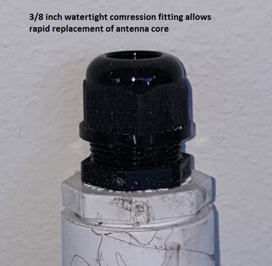
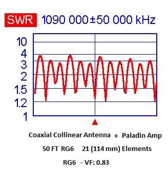
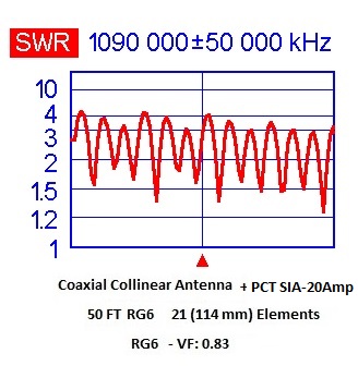
Current designs have 20+ elements enclosed in a 2.8 meter pvc radome constructed in 3 approximately equal segments lengths of 1 inch, 3/4 inch, and 1/2 inch pvc pipe. The 1 inch segment is reinforced with a 3/4 inch liner, the 3/4 with a 1/2 inch liner and the 1/2 inch with a 3/8 cpvc liner. The 1 inch base includes an extra 30 cm reinforced segment for mounting.
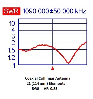
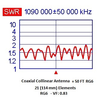
The cable used in this data set is Perfect Vision RG6 solid copper core.
.
Tests were run to compare various combinations of antenna, cable, and 2 different amplifiers
They were; 1: At the antenna (including complete data set), 2: Antenna + 50 ft RG6 cable, 3: Antenna + Paladin amplifier + 50 ft cable, 4: Antenna + PCT amplifier + 50 ft cable.


@elpipila:
This is great!
Your tests have proved it to be good.
Next step is trial run.
Waiting for trial run results.
Good looking antenna! And interesting results for the satellite line amps on 50’ of RG6, whatever their output impedance is its not 75 ohms.
I’m not sure that it matters that much though, if you have a longer cable run and or you live in a less than optimum location and the input noise figures of the amp are better than the SDR dongle you will still have a net improvement.
Do you happen to have a SWR plot of 50’ of rg6 connected directly to the COCO?
Same RG6 cable as the antenna with compression connectors.
Thanks elpipila
I obviously didn’t read the descriptions in your first post well enough…
Will have to have another try at a COCO if I can find some of that perfect vision coax, its not common here.
try soldering the sections together as well if you aren’t already it makes them much more consistent.
https://www.dropbox.com/s/kgijjqjgbctxn72/WP_20140423_002a.jpg?dl=0
Some appear to have the magic touch for COCOs and some don’t (i’m with the latter group) I tried soldering one up out of Belden 213 but it was still rubbish ![]()
The only way i have found to make a decent collinear was using the printed micro stripline technique mentioned in this thread.
Getting the collinear tuned and performing better than a 1/4 wave still requited filing down the lengths of the individual striplines .5mm at a time then re-soldering the sections and checking impedance match with a noise source / directional coupler.
My CoCo is directional ![]()
![]()
I’ve always had a bit of an area to the NE of where I’m located where the antenna cuts off at about 170nm. All the other quadrants it gets out to almost 200nm. Just for fun I turned the antenna through 180 degrees and suddenly planes beyond 170nm popped up in the NE.
Now I’m not sure if the change is due to the flight paths or the change in direction of the antenna.
I’ll monitor for a couple of weeks.
If abcd567 is reading this
If the coax segments are not joined at exactly 180 degrees to each other, would that cause this anomaly?
@triggers
Very strange! Never came across a directional CoCo.
Perhaps a picture of the directional beast in it’s roosting position would be of some value. ![]()
Cheers!
LitterBug
Hi Nigel, @Devonian . You are my nearest feeder site and i’m intrigued by the difference between your 2 feeder stations. One is on a par with mine and the other has about a 30% increase on mine… Whats the difference between your 2 stations…is it antenna or elevation?
Kind Regards
Neil
Hi Neil,
The one with the higher count is on a R-Ri3 + RTLSDR dongle + RTL-SDR Blog LNA + outdoor 5db gain antenna on the gable end of my bungalow roof, coax is CT100 and about 6 metres total length.
The lower count one is my original R-Pi + RTLSDR dongle from 2015 and is in the attic with no preamp and currently on a homemade ¼ wave ground plane antenna with 1 metre CT100 coax – I keep it running just to see how long it will go as my ‘streak’ is continuous since starting this one (2 thousand+ days so far). The attic antenna is about 2 metres away and 2 metres lower than the higher count one. I also use this setup for occasional antenna experiments as it’s easy to get to.
My elevation is ~100 metres ASL and reasonable take-off from NW thru SE but nearby hills severely block me otherwise.
I’m located at the top of Canal Hill, if you know the area.
Regds,
Nigel