This morning I woke up and I had the surprise to look outside and see the ADS-B antenna cable laying on the grass. I examined the end and the end wasn’t broken, just somehow unscrewed itself from the amplifier output and fell. I could see some traces of water ingression too in the head, I guess it was a slow process.
I figured out that it was my fault, when I raised the antenna, I have left the antenna cable dangling down under it’s weight, supported by the connector. Bad. I should had made a loop to support the cable weight.
Luckly today is very warm outside, 70F (21C) at 9AM.
So I took the antenna down to reconnect the cable and, with that occasion, to replace my no-name amplifier with the “RTL-SDR Blog ADS-B filtered” one that was waiting in my drawer for a few months.
This LNA requires lower voltage than my previous one (that had incorporated stabilizer), so I set my power supply to 4.5V.
The caulking that I had before on the bottom holes of the box became a brittle dust, even if it was “silicon” based.
I did clean the connector with some isopropyl alcohol and added the supporting loop.
Checked the antenna functionality at ground level and… it works! Up on the tree it goes!
The results are somehow disappointing. The gain of the new LNA is lower than the gain of my previous no-name one. With my FlightFeeder I had to go from 12dB to 33dB! With my Airspy R2 I was already at 21, so… can’t go higher.
Maybe when I feel less lazy I will try to trow a paracord over a higher branch…
What do the graphs say?
Gain alone doesn’t mean too much.
If you are somewhat tech-savy, you can measure the current the rtl-sdr LNA is consuming and adjust the voltage so it consumes 150 mA.
With that number it should be at full gain.
Use the multimeter set to the A range instead of the mA range, it has lower resistance, that way you don’t need to account for the series resistance of the meter.
As for the LNA, i’ve never seen that sticker on a rtl-sdr LNA unit, but maybe it’s new.
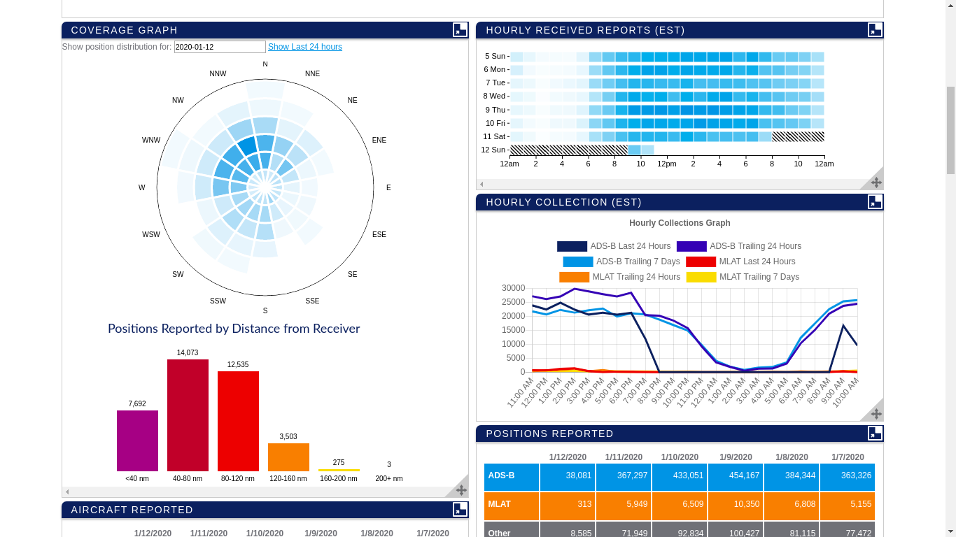
Comparing the range distribution of your positions on FA:
(comparing the column diagram and pi diagram on the left)
Seems like the proportion of positions far away hasn’t changed.
The lower number of positions close by might be due to the day of the week or you have set the gain too high, i somehow remember you always setting the gain sky high
Yeah, i have a FlightFeeder too. That’s where I saw that I needed to raise the gain.
I am reluctant to try directly bias tee from airpsy because… it’s expensive.
If something happens on the outdoor portion, I can handle frying a power supply, but not the R2.
Inside, I have a gas lightning protector between the bias tee output and receiver inputs.
Not what i was suggesting
Just meant getting rid of the splitter to increase the signal.
I’m sure FA won’t mind letting that sit on the shelf as long as you feed with the Airspy?
(well i don’t know actually)
Anyhow with that long of a cable, just go up to 5 V supply voltage, the LNA shoudn’t have an issue with that even without the long cable run.
(or measure the current going from the power supply into the power injector)
I could not measure the voltage at the LNA end, that would make me feel fuzzy and warm. My adjustable power supply has steps: 4.5, 6.0, 7.5, 9.0… So the next up would be a 6.0V.
In my other LNA I have build inside that regulator and looking at the new PCB it seems that it was designed to accept a stabilizer IC too.
I’ll go out to measure the current now.
LE: It was 124mA and the source output was 4.6V
I have raised the voltage to 6.0 setting, the measured voltage at the injector tee is 5.8V and the current 164mA.
The gain went up significantly. Hmm… too much current/voltage?
I’d adjust it to 150 mA and be done with it
Maybe even 140 mA.
As i said previously be aware measuring the current, the ampere meter is an additional resistance.
You can of course measure the voltage after the multimeter and restore that once you have the ampere meter no longer in series.
Oh i understand now, you only have discrete settings 4.5 V and 6 V.
You have a 5 or 10 Ohm resistor lying around?
That might be the ticket combined with 6 V.
If you are fancy you can put a capacitor behind the resistor to reduce the ripple
With the series diode the voltage at the injector is now 5.2V (like I said the “6V” position was actually 5.8V). Allows for enough voltage drop to 5V and is not dangerously close (or over) to the 5.5V max.
The gain seems to dropped a little (some 2-3dB), but it’s hard to tell. And I don’t think is important.
I forgot to measure the current before soldering it in, but I think that’s perfect, thanks for suggestions.