The cpu utilization is just one core on your Pi, not all cores. I also get 80% with e at 10.8 on Pi and CM4.
I don’t know about you, but I’ve been fooled too many times to judge any small change with less than a day or two of data at least. Unless you clearly foobar something, it takes a lot of data to prove something.
The 3db to 6db gain increments shouldn’t be too dramatic on positions stats. So this is hard to evaluate quickly. Going to gain=19 with the Uputronics possibly isn’t the most optimal level for your station, but I also think you won’t be certain until you can test over full days trying a tweak here or there over weeks.
That’s just on the pi, so only the pi will get hotter
And comparing message rates like that is completely futile.
If you had graphs for the airsquitter you could look for changes in the ratio between stations.
I suppose you can look at the live value but you really need some average over time if you compare two stations.
Well no one ever suggested using a super low gain with the uputronics LNA.
Rather incrementally decrease gain until the weakest signal displayed in graphs reaches a certain value
And by that i mean the approximate trend of the light blue line in the signal graph.
In your last picture i’d call that roughly -18.
Getting that line down to even -35 probably means a gain of no lower than 17.
No matter i doubt very much you’ll see any difference from gains between 17 and 21.
The most effect the lower gain will have is probably having a nicer signal graph and RSSI values in the table that give you a better idea of actual signal strength instead lots of planes clamping at 0.0 dBFS.
And if you see any difference it’s very very very likely you’re just imagining it
Even comparing 2 days to the previous 2 days is futile by the way.
Mostly you need a similar performing reference station … in an optimal case build a graph that plots the ratio between message rates … and so forth.
The Airspy is new to me and i need to “learn” how to use it. Completely different than the other devices i used so far
I will now simply do longer test runs of at least a day per change and i will include the AirSquitter with the Antenna at the same position for comparison
The conditions changed a lot on Friday as the EDDF approach is now from my side.
This changes the reception significantly and it’s simply not comparable.
What i have recognized in the FA stats is that the number of positions for Aircraft > 320km distance has been increased by three times compared to any other day before.
But keeping an eye on this as well.
That’s what i am trying now.
I am building a relation to the overall values per day (currently higher due to the approach change) but the > 320km is at least two times higher than last week.
Yes, the first one with the lower number is my spare device in my home office (indoor) while the second one is combination of Airspy and Jetvision antenna mounted outdoor.
But for testing i can bring the indoor device to the same position outdoor. But that will be step 2 as it’s not that easy
EDIT: I know you don’t like snapshots, but this i haven’t seen before. A message rate around 1000 with less than 50 aircraft.
Even not on my AirSquitter
The peak range of your graphs giving me 184NM, another thing which i did not achieve before. Not that much, but an improvement. It fits to my position comparison on FA
Mind you, 10.4 dB of perfectly linear scale at full bandwidth. Actually, we don’t need that much linearity when decoding OOK signals and we don’t use the full bandwidth, so the other not-so-linear bits to complete the 12-bit output of the ADC also contribute to the final dynamic range after some fancy DSP. We easily end up with ~16bit data at the bit-decision stage.
While i am doing the long term test and playing with the settings, which values do i have to check for getting an idea how it is performing per setting?
Which settings beside gain are the most important ones?
Thanks, that is not shown in the Airspy datasheet, not unless you really dig into Philips/NPX datasheets.
Anyway, I think that huge dynamic range makes the device seem to be “insensitive” to the RSSI numbers, that are adequate for the 8 bit ADCs.
I added a splitter in my signal path, after LNB, so I have the same signal applied to a Flightfeeder (reference) and my Airspy system. Yes, the feeder attenuates the signal by -3dB, but I have plenty of signal past my LNB.
If you can have many receivers connected to the same antenna/LNA, you can make more targeted measurements and learn faster. You would then need a splitter.
Will see what i can do. The environment does not allow two receivers permanently there. And i have to check where to get a splitter (and how to explain that additional investment to my wife )
I use a cheap one. I know is not perfect, instead of the theoretical -3dB I might have -4, -5dB… IDK, it works for me. Something like this (just choose the correct “genders” and pins):
Which also means the two devices under test might be getting a differing signal and both devices can interfere with each other if they produce noise on their input.
Just to explain why those cheap ones aren’t good.
Mostly they work but i wouldn’t rely on something like that for a real comparison as you couple the systems too strongly.
I doubt it. Every decent chip has to pass FCC rules and not radiate into receiving antennas.
If that would happen, even if you have two separate antennas, they will influence each other.
IMO the only disadvantage is the additional attenuation by mismached impedances. However the LNA output impedance capability helps a lot with that.
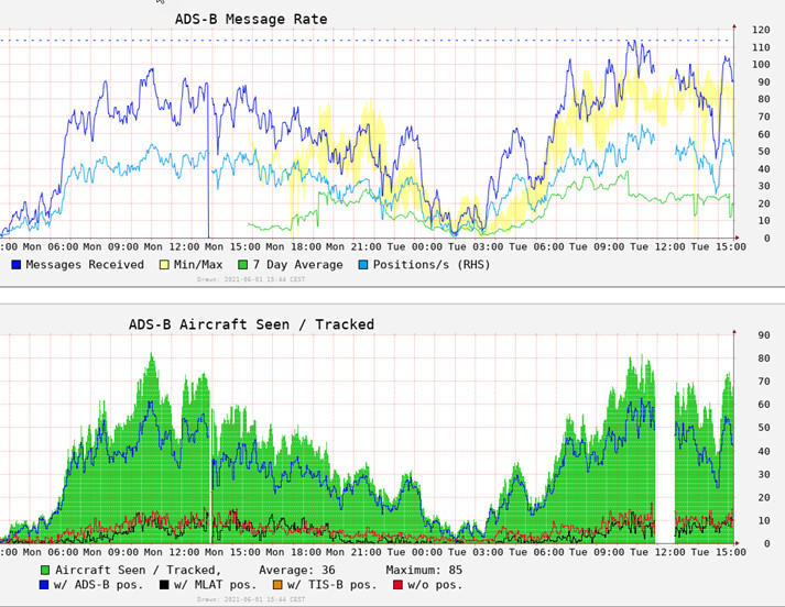
Quick update (i know @wiedehopf does not like these comparisons )
last 2 days of data.
Changed the Stick yesterday at around 1pm, unfortunately there was already a downtrend of aircraft seen.
The gap today was caused by a planned downtime (cleaning balcony).
Setting of the device is 12 MHz, Gain 19, -e switch set to 10.8 following @SoNic67 suggestion.