
Please see page 13 of this .pdf document by cisco
.
Looking at the 3D plots of the Yagi in the paper you highlighted, it looks like it doesn’t matter about the orientation of the Yagi. It an be mounted with the elements horizontally or vertically and you still get the same gain. Is that right?
For 1090Mhz I thought the elements must be vertical for best gain.
![]() [The beekeeping season is coming to an end so I’ll be more active on the forum again]
[The beekeeping season is coming to an end so I’ll be more active on the forum again]![]()
1 Like
This is not a plot of polarization vs gain, but direction vs gain.
The direction and the polarization of a signal are not the same. Imagine the incoming radiowaves as a sort of long band that must roughly fit through a slit, the antenna. Now you can twist the band (here the image does not quite work anymore) and you will roughly get a reduction in strength to how long that band appears in the direction of the antenna. You know trigonometry and the cosinus stuff. But i think you need to square it for power so it falls off proportional to the square of the cosinus of the angle the transmitting and receiving antenna are twisted relative to each other.
Of course you put the element vertically, all the aircraft have their antennas vertically as well.
On line-of-sight (LOS) paths, it is most important that the polarisation of the antennas at both ends of the path use the same polarization. In a linearly polarized system, a misalignment of polarization of 45 degrees will degrade the signal up to 3 dB and if misaligned 90 degrees the attenuation can be 20 dB or more.
Polarization in the same plane as the elements of the antenna.
So a vertical antenna (i.e. one with vertical elements) will receive vertically polarized signals best and similarly a horizontal antenna will receive horizontally polarized signals.
That Yagi plot is wrong because it shows that, no matter of orientation, the Yagi will have gain.
I know for a fact that, in a horizontal polarized situation (TV stations), if you install the antenna with elements vertical, you get almost no signal. You need to install them horizontally.
With the ADS-B signals,antennas are installed on airplanes vertically. The ADS-B receiver antenna should have the elements vertical too.
PS: All FM radio is either circular or dual polarity because they hope to program to vehicle antennas (Vertical) and home antennas (Horizontal). FCC allows that.
Dual polarity requires twice the transmitter power for FM, and circular requires more transmitter power as well, but not quite as much as dual polarity, and of course, broadcasters want to avoid running more power than needed due to power costs.
@sonic67 The Yagi plot is not wrong. It assumes polarized signals in the antenna plane from every direction.
Yes you heard me right that is possible. Well if the sender is directly above the antenna i suppose it’s not really possible. But regarding that plot, the two directions you are CERTAIN should have different gain, it is perfectly possible.
The airplane is somewhere on the horizon with it’s antenna vertical. If it moves 5 degrees up or 5 degrees to the right seen from my position does not change the polarization now does it?

Ah yes, I didn’t have my thinking head on this morning.
Welcome back. Missing you for a long time.
Those are diamond loops, they are not polarized. I am talking about Yagi.
How about if you rotate Yagi antenna on horizontal?
If those plots are not wrong, then they are at least confusing, because they don’t talk about polarization of the test field. That’s not usually how is measured IMO.

So for ads-b you would rotate the antenna 90 degrees as already stated. Doesn’t change the graphs at all i believe they look just about symmetrical on that axis.
I would say they just silently assume that you know the polarization of what you are receiving and will adjust the antenna to match that.
What fig. (b) shows is that the radiation pattern (beam) looks like a reverse cone (give or take). The base of the cone will get bigger as the signal moves away from the antenna.
The beam width can be changed by adding or reducing the number of directors and reflectors. It’s always going to be 3D, i.e. x, y, and z axis.
As I mentioned earlier, take off angle is also a factor. Using the same theory described for ADS-B range, where the signal hit the ionosphere will determine the attenuation (loss) and the number of hops the signal will do.
My ‘background’ is HF, as the frequency increases other factors may come into play.
The diagram “(a) Yagi Antenna Model” shows elements horizontal.
All the radiation diagrams are based on "Arriving signal Horizontally Polarized, irrespective of the direction from which these arrive: From front of Yagi along its axis, from back, or at an any angle to axis from sides, from above, from below: All horizontally polarized.
That’s right, horizontal polarization does not mean the signal will only arrive from the front.
Again, use the mailbox with the horizontal slot analogy. One can still insert a letter horizontally from different angles, not just straight in.
If you try to insert the letter vertically, it’ll still go in, but with some ‘losses’.![]()
Yagi is basically a dipole fitted with parasitic elements directors and reflector to make it more directional than its only active element (to which coax is connected). This active element is a “dipole”. The dipole is also used to receives the signals polarized along its two limbs.

Hey… How about constructing a 1/2 Yagi, with only one set of vertical lambda/4 elements? The parasitic elements also at 1/2 sizes and can be put around at some 90 degree angles, no reflectors. We don’t need the bottom lobes.
Add a ground plane below…
I’ll try it after the hurricane rain passes.
Sounds like you are talking about a corner reflector antenna.
No. I am talking about a Yagi cut in half longitudinaly. Installed vertical. So it doesn’t require symmetrical to asymmetrical adaptation. And smaller to build.
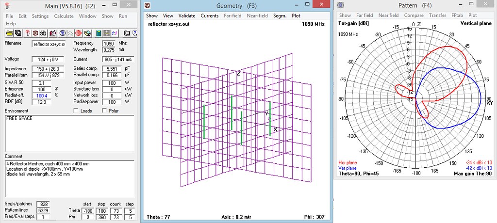
A SET OF 4 VERTICALLY POLARIZED CORNER REFLECTOR ANTENNAS, ONE IN EACH QUADRENT.
Each of four meshes are 400mm x 400 mm
The dipole at X=100mm, Y=100mm
There are 4 dipoles, one in each quadrent.
For simulation, only one dipole is excited (the one in XY quadrant).
Good Radiation Pattern and Gain (13 dBi)
SWR is very high (3.1)
CLICK ON IMAGE TO SEE LARGER SIZE
Can you simulate one that doesn’t have dipols? Like the spider or cantenna, they don’t have dipols, they are just one lambda/4 stick… add four passive elements in front.
I would calculate their sizes now, but I am too tired, maybe tomorrow… during the tropical storm rains.
Yagi’s antenna is difficult to construct so that it conforms to theoretical calculations. The bi-quad antenna (and array) is simpler and allows the deviation of the sizes from the calculated values.
As variation:
4xQuados - 14.7 dBi
6xQuados - 16.5 dBi
8xQuados - 17.6 dBi
http://3g-aerial.biz/konstruktsii-antenn/vsenapravlennye-antenny/antenna-quados


2 Likes