
No, they are not that bad, but certainly not 12dB either.
Observably better than a PCB Dipole, but not 3dB better.
You’re saying the performance of this stripline antenna is “underwhelming” but it’s better than the cantenna? Can you elaborate regarding message counts, range and number of planes tracked with each antenna at your location? Thanks.
(I wonder what they’re referencing the supposed 12dB of gain on, a 1/2 wave dipole, a 1/4 wave ground plane, the theoretical isotropic antenna, or something else?)
the ‘cantenna’ is a fun, rainy sunday afternoon project, but is not a performance antenna. The fact it often out-performs the PoS mag base antenna provided for tv reception only goes to show how bad the mag base is.
My comparison site has been offline since last year (I’ll bring it up when I get back to it).
To be honest, the performance simply wasn’t different enough to warrant a lot of effort
Don’t overthink it. 12dB is just a number snatched from the air.
It’s just a marketing claim they hope no one will test.
Have a play when yours arrives and make up your own mind.
There’s absolutely nothing wrong with the cantenna. It’s basically the same as the 1/4 wave ground plane antenna with sloping radials which is a tried-and-true antenna design that offers around 2.4dBi of gain. This style of antenna (the sloping radials style, not the beer can style, but electronically they’re pretty much the same thing) is in use worldwide for various commercial and amateur radio applications. It took me less than an hour to build mine, a few minutes to get up in the air as high as is possible here, and I was seeing more airplanes from farther away. They’re great easy-to-build and inexpensive starter antennas.
The mag-mount antenna with its various screw-on elements is meant to be more of a general-purpose starter antenna just so people can begin using their new SDR dongles right away. The antennas are wide-band so they don’t perform optimally at any given frequency except perhaps by accident. Antennas are tuned circuits but things like the telescopic whip on a mag-mount are more like probes sticking into the air, they’re not really even antennas. However, they’ll usually pick up something and any antenna is better than no antenna.
Regarding the stripline, the description says it has four 1/2 wave antennas, so I still have no idea how they came up with “12dB” of gain when a 1/2 wave antenna has 2dB of gain. Even if they’re phase-matched so they’re additive it would only be 8dB total. Still, that’s better than the 1/4 wave ground plane’s 2.4dB so I’ll take it.
The stripline should arrive within another week so I guess I’ll find out what it’s like then: see if it does anything at all to increase my range (doubtful, unless it sneaks out at night and dynamites neighbors’ houses and cuts down trees) and numbers of messages/planes. As I’m not feeding FlightAware I don’t have a stats page so it’ll just have to be anecdotal as VirtualRadarServer’s ad hoc report form doesn’t have message count or distance as search criteria. I suposse I could do an SQL query both before and some time after changing antennas, sorted by the two criteria, and compare the two results, and I think I’ll be too anxious to start using the new antenna to have time for SQL queries.
Quote from an old post (August 2015)
NOTE: Simulation results give only indicative figures. Reliable results are those which are obtained from actual measurement, using VNA + Directional Coupler for VSWR, and Anechoic Chamber for Gain.
1 Like
That’s interesting. I thought it was a form of 1/4 wave ground plane with sloping radials, which per all the research I’ve done (ham radio sites, excerpts from the ARRL Antenna Handbook, etc.) plus ancient past experience normally has around 2.4dBi of gain. Is your gain measurement dBi (referenced to a zero-gain isotropic antenna) or dBd (referenced to a half-wave dipole?)
(1) The gain figures are in dBi
(2) It is not a measurement, it is result from simulation of the antenna models in a computer software. As I have mentioned in note, these computer simulation results are only indicative, and not accurate enough to blindly rely upon.
(3) The purpose of the old quoted post was comparison, i.e. to show that results of simulation of both the1/4 wave ground plane with sloping radials, and Cantenna are more or less same.
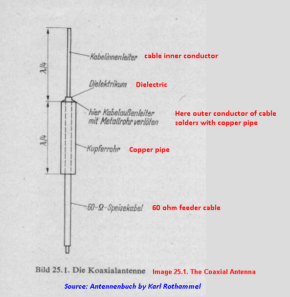
SKETCH 1 of 2: Die Koaxialantenne (The Coaxial Antenna)
SKETCH 2 of 2: Cantenna

Cantenna is a hybrid of ground-plane and vertical-dipole, with one leg of it acting as a balun. This balun type is known as a bazooka balun or a sleeve balun or decoupling sleeve. Please see above sketch.
When a dipole is fed by a coax, due to common-mode current on the coax shield, the coax itself becomes part of antenna and influences antenna performance. In order to eliminate/reduce influence of coax on antenna performance, the common-mode currents on coax shield should be eliminated or at least minimized.
This can be done by making the impedance to common-mode currents on the coax shield very high while keeping the feed circuit impedance to dipole unaffected. This is what is done by bazooka or sleeve balun. As a result there won’t be much common-mode current, while the feed current to dipole will be unaffected by the balun.
@abcd567 Ah! As my cousin’s uncle used to say when working on motorcycle engines, “NOW I see! NOW I understand!” The bottom of the can’s the ground plane while the sides are a decoupling sleeve. Thank you for taking the time to explain to me. Also for designing the cantenna in the first place: it got me started seeing more airplanes at a longer range vs. the mag-mount antenna.
Does the decoupling sleeve negate the need for a choke balun in the coax near the antenna then, or would you still recommend one?
You know how the bottom of fizzy drink and beer cans is rounded inward to help prevent the can from bursting due to pressure from the carbonization? I wonder how it would affect the radiation pattern and impedance antenna if that were forced outward such that the top (ex-bottom) of the can was rounded slightly upward or “exdented” rather than indented? I’m guessing it would probably impact the impedance more than the radiation pattern, possibly making it closer to a 50 ohms antenna rather than 75 ohms and perhaps giving a somewhat better VSWR when using, say, LMR400 coax?
Never thought of it. Most likely adding a choke balun wont harm, even if it does not benefit. Only by trying it one can find.
One can only know by trying it. I never tried it.
By the way, I did some research on isolation chokes which is what the “choke balun” is. Their purpose (along with similar ferrite-core chokes on the coax near the antenna) is to prevent a transmitter’s RF energy from being induced into then radiated by the coax shield which otherwise can act as an inductor. Otherwise you get power being radiated in unwanted directions which reduces efficiency, causes interference to local receivers like TVs, and can cause RF to leak back into the shack. They’re not really needed for receive-only antennas as the signal strength of received ADS-B and other radio messages is extremely low compared to, say, a 100w transmitter. They don’t hurt anything other than requiring longer coax so you can form the loops and the longer the coax the more loss it has, but they don’t help anything either.
I still haven’t tried “outdenting” the cantenna yet to see what happens. I’ve been using one of those Chinese-made PC board stripline antennas in the white plastic housing instead of my cantenna. I still plan to try it someday though.
Agreed, I wouldn’t choke an ADS-B aerial, there’s little point.
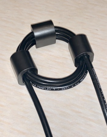
Winding chokes can be quite satisfying though. Here’s one of many GM3SEK chokes I’ve wound.
1 Like
And know I will come around the corner and tell all you guys that you have forgotten something important ![]()
Ok lets start…
the polarization of the waves transmitted are vertical…right ?
ok…
whats happen in a U-turn or sharp curve ???
I am sure you will loose extremly fieldstrength
I do not want to open a new discussion about the normal rod antennas …I had before a lot with so called experts…and also I promissed that I would like to develope a new antenna design which will works perfectly for ADS- B no filter is anymore needed which will generate additional losses.
check my test I made a few days ago

You can use that antenna also as sector antenna with a beam like a yagi antenna.
Because of all the copy cats from asia…you are discuss this rod antennas here…this are bad replica antennas …sometimes you will have luck and they are working sometimes they do not know what they do …
anyway
have fun with your equipment and stream on
Bill2002
If you want more design:
Or something looking different:
Beside that i do have a TEN90 here (the red one). This is missing at least 25% of performance compared to a Vinnant or Jetvision. GNS can’t perform miracles
fox…what do you mean with performance ?
It is always the same discussion… with you guys how do you compare how do you measure ?
If you are happy with your antenna from other companies everything is ok. Why not.
The thing is that we have here a new antenna design which I have tested. The performance against a rod antenna is very good. The antenna is more flexible because it can be used also as sector antenna. The antenna is independent against neighbor frequencies and it is independent against polarization. Beside very small and can be directly mounted on metal
in all directions you want.
regards
Bill2002
By simply replacing my outdoor antenna with the red TEN90, i have an immediate drop on message rate and aircraft seen.
In addition the gain must be set at least two steps higher.
No idea what kind of discussion you mean
Fox… I do not know which kind of outdoor antenna you have.
I believe you are comparing apples and pears.
Patch antennas have very limited uses in my view. Usually in places where space is limited, like automotive, aircraft. They come with integrated LNAs.
The directionality (sectorization) is not really needed for our application either.
And yes we are comparing apples and oranges, but then… for our application is the end result that counts. Side-by side comparations.
SoNic67
you see the video ? you see the application, the range …etc.
I have developed this antenna by myself and I am working with antennas a long time.
There is no need for an integrated LNA for what ? You are mixing something maybe with GPS patches …sometimes it is better to use an LNA depends on the matching
Side by side with the same equipment in the same time parallel so you need to have two ADS-B Receiver which are doing realtime processing and not storing …no port sharing nothing only ADS-B receiving…then it may work with comparing esp. with independent receiver like jetvison or GNS have. Then I am with you ![]()
I believe that you are very focused on receiving long distance…this is not I am focused because if I will see one or two frames of planes which have 550km distance in 10km hight so what ? It is catched one time because of whatever conicidence. For me receiving all possible framerates of a plane are more important …so everyone has his goals ![]()
regards
Bill2002
I did, but from that high location is impossible to tell how a normal colinear antenna would perform.
In my experiments the antenna gain was not as important as the actual location - height to clear the close-by obstacles.
Same here. I found out the dynamic range and SNR of the receiver ADC has a lot to say in that respect. I have switched from 8 bit receivers because of that.