Back to topic:
Did you make 19 inch long Ductenna? If yes, how it performed compared to the 10 inch one?
Sorry, I missed your request to simulate 19 inch one. Will do it tommorow.

Back to topic:
Did you make 19 inch long Ductenna? If yes, how it performed compared to the 10 inch one?
Sorry, I missed your request to simulate 19 inch one. Will do it tommorow.
No I never extended it and I’ve still got the original pointed out my window. I’m getting better omnidirectional performance than I was with the spider for some reason, at least my stats have improved. I’m guessing it has more to do with being inside the house than anything else. I used to have this stuff in the attic but it got so hot up there in the summer I was a little worried about something going wrong and starting a fire. The raspberry pi was probably OK but I didn’t know if the power supply and pro stick were rated for high temps. So that’s why it’s in a spare bedroom pointed out the window now.
Sounds like your ground plane antenna was causing some receiver overload.
The waveguide antenna is attenuating the received signal from all directions except the one it’s pointed at.
(That’s a generalization, as the beamwidth isn’t pencil sharp. e.g. Signals 30 to 45°, possibly more, either side of beamwidth center won’t be attenuated a great deal)
Are you talking mobile signals. Or really overload from ADS-B signals? The second possibility sounds unlikely unless he was using 3 LNAs in a row. (Even that works with a gain of 2 or something set in software)
Any signal. It’s easier to overload a receiver than one would think, especially if internal gain is set high. Doen’t do any harm, just has a negative effect on receiver sensitivity
He says he’s getting better omni-directional performance than he did with a ground plane antenna.
Given a waveguide antenna has a pattern that’s significantly different than a vertical monopole,
(ground plane antenna) and that signals arriving at any direction other than the open end of the
waveguide will be attenuated, it sounds like the waveguide antenna is attenuating strong signals at the receive frequency, and/or any others that could be considered interference, enough to give him that improved receiver performance
I just always assume people check that they are not running their gain too high.
With the common dongles even the blue stick you can basically run at maximum gain and still get good numbers.
My assumption would be the ground plane antenna was poorly executed (it is easy but mistakes can always happen) or there is some mobile phone mast somewhere the new antenna is attenuating most ![]()
Also could be that the waveguide antenna is just doubling as a frequency filter.
Actually that sounds like the most likely explanation.
I’ll probably rerun my noise scan i did to compare the prostick plus and the filtered LNA i use with my homemade colinear that has poor gain overall but might be filtering interference pretty well.
(only using the prostick plus and filter though as that’s how it’s connected as the moment. Also the antenna is indoors as i don’t want to mount that colinear it’s just not worth it at the moment)
Essentially what I was speaking of:
In a sense, an antenna is a filter, a band pass filter. Depending on variables like frequency, type of antenna, how much care was used in building it, etc. it can have a somewhat flat response curve, meaning its response is broadband, or its response curve can have steep skirts like those of an actual filter.
At 1 GHz, it’s fairly easy to design one that has a narrow pass band. (building it is another matter)
e.g. a quarter-wave at 1090 is 65.4 mm. Trim that element 0.3 mm too short and the resonant frequency just went to 1095 MHz. Trim it a full mm too short and you wind up with an element resonant at 1106 MHz. Two mm too short and it’s resonant at 1124 MHz. The further from resonance-at-1090 Mhz the antenna is, the weaker the signal it delivers.
Same idea applies if the element is too long, i.e. it’ll be resonant at a frequency lower than 1090 MHz.
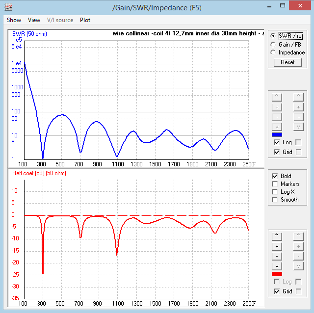
Frequency Sweep (From 100 MHz to 2500 MHz) of Wire Collinear Antenna and 1/4 Wavelength Ground Plane Antenna.
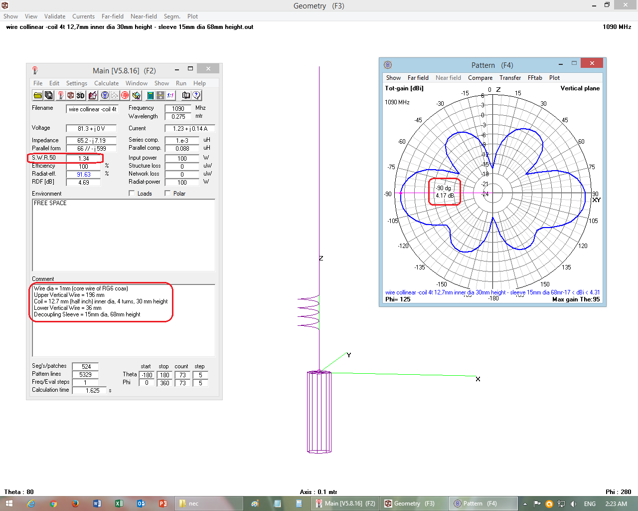
The frequency sweep results of a high gain wire collinear antenna show that it not tuned only at one frequency, but also tuned to multiple frequencies and performs fairly good at these frequencies as well.
This characteristic of collinear antennas is disadvantageous for single frequency reception, and the RF signals picked from all these multiple tuned frequencies necessitates an tuner circuit or a filter at front end (i.e. between antenna and receiver).
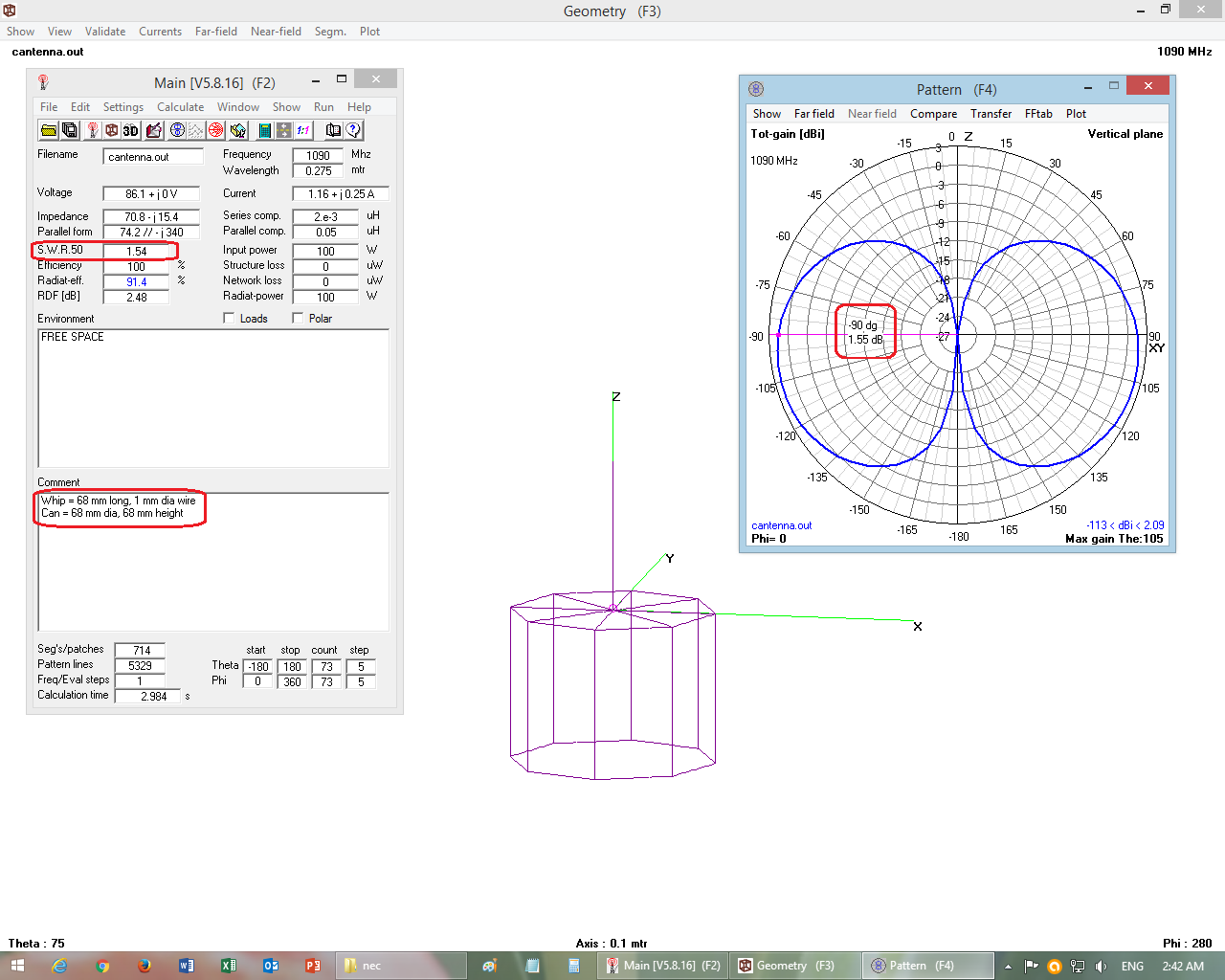
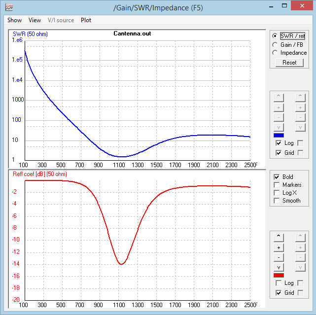
The frequency sweep results of a 1/4 wavelength ground plane antenna show that it gives good performance at and near its designed frequency only, and at other far away frequencies its performance is poor. Hence the 1/4 wavelength ground plane antenna picks very little harmonic and sub-harmonic frequency signals.
.
.
WIRE COLLINEAR ANTENNA WITH DECOUPLING SLEEVE
Click on the thumbnails to see full size images
 .
.  .
.
.
.
1/4 WAVELENGTH GROUND PLANE ANTENNA (Cantenna)
Click on the thumbnails to see full size images
 .
.  .
.
Not tuned (as tuned denotes the desired frequncy) but responsive.
And as you’ve indicated, response on frequencies other than the desired receive frequency is almost always not a good thing. Maybe semantics, but that’s why the terminolgy exists. ![]()
I’ve built several spiders over the years and even though I make them with the same specifications and try to be consistent, it’s sort of fascinating to me how they will vary in performance. As far as optimization goes, I’ve relied on the optimize_gain.py scripts and normally select the gain that sees the most planes since that seems to be the metric for scoring on FlightAware. Installing the FA filter has generally never improved my performance, oddly enough, and when I used to have the hardware in the attic I could often do better with the old orange stick than with the Blue Pro Stick with or without the filter. I’d always hoped to see the dramatic differences that abcd displayed (so long ago when the Pro Stick came out) but they just don’t seem to materialize in my environment.
One thought on the current performance takes me back to the fact that my house has foil backed wallboard and aluminum siding. Pointing out the back window with the ductenna makes me kind of visualize a dish setup where I could exclude the interior of my house and focus the beam towards the window. Another factor helping the omnidirectional case could be that the room ceiling is drywall, above which is fiberglass insulation, then plywood and asphalt shingles. So the shielding effect from my wallboard and siding surrounds the antenna in the horizontal plane but it’s mostly open to RF looking vertically upwards.
I’ve not paid a lot of attention to receiver overload since I’ve been chasing the configuration that gives me the most planes, but some of the high gain configurations have visibly excluded nearby planes in return for more distant ones. I always assumed they were overloading the receiver.
Correct assessment. The foil backed insulation is acting similar to a Faraday cage (a very leaky one!)
and shielding your antenna, which as you’ve observed can be a double-edged sword, so-to-speak.
In general, a filter is effective only in an environment where signals other than those at the desired receive frequency manage to make it into the receiver. (e.g. front-end overload, third-order products)
That is normally the tuner will shut them out?
SUPERHETRODYNE AM/FM RECEIVERS
Have 2 Stages of Tuning/Filtering

.
IF COIL IS A BAND-PASS FILTER
Tuner’s heart is actually an variable filter, using a special capacitor, which value can be electrically changed. It’s actually a type of diode (varicap) , reverse polarized.
But being variable, single pole LC, is not as effective as the fixed ones (multiple poles, SAW, etc.)
Right.
In a superhet receiver:
Sensitivity is developed in the receiver’s front-end (RF section).
Selectivity is developed in the receiver’s IF section
which works well unless the interference is at or near the desired frequency.
Unless it’s a triple conversion receiver. ![]()
(usually found only in high-end equipment)

.
.
Are you going to model the longer antenna with a horn?
If so, try it with a horn considerably longer than 3 inches. That should improve the SWR significantly.


