Ideas for optimizing the performance of your ADS-B setup.

The system consists of a Raspberry Pi, Flightaware’s PiAware (SD Card) V1.20 running with dump1090-mutability.
The performance of my ADS-B monitoring system has been improved dramatically over the past several weeks using a homebrew coaxial collinear antennas of eight (8), and then eventually twelve (12) elements. The type of coax used to make the antenna was RG-6 quad shield coax. The antenna is mounted on the roof of the house with the base of teh antenna at about 20’ AGL and fed with 50’ of RG-6 quad shield coax. The ADS-B antenna shown in the photo below is the eight (8) element vertical coaxial antenna version just to the right of the weather station.


Figure 1
From memory the maximum reception distance of the telescoping antenna was in 50 - 100 NM radius with the majority being in the 0 - 50 NM radius. Unfortunately, I didn’t take any performance data of the telescoping whip antenna that came with the dongle to show the total system improvement that has been achieved over the past month because I had no intention of using it as a permanent installation. But that data would be an interesting comparison.

After doing some research on impedance transformation a twelveth wave coaxial transformer was made using RG-58A coax. This should help match the 75 ohm RG-6 coax to the 50 ohm impedance of the SDR dongle radio.

The following plots from the flightaware website data show the distribution of the aircraft received using the 8 element coaxial collinear antenna. My system has been activated 24/7 since the 10th of January 2015. I operated using the whip antenna that came with he dongle until I received the Raspberry Pi and the cables that I had ordered.
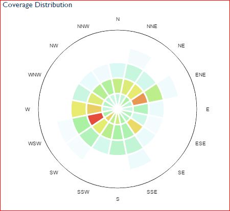

Figure 2
02-04-15 eight (8) element collinear distribution
The high traffic areas (Red and Dark yellow) are the locations of VORs. So the maximum range is 150 NM for the barebones 8 element antenna and reliable distance out to 100NM.


Figure 3
I then on 02-19-15 I decided to add four (4) additional elements to another coaxial collinear antenna that was built out of RG-6 direct burial polyethylene core coax this time. This was a little easier to work with than the quad shield RG-6 for making the antenna.


Figure 4
On 03-01-15 the twelve (12) element collinear was improved by adding a satellite diplexer which has a bandpass filter in the range of ADS-B frequencies. This immediately improved the message recption rate at the time from 100/second to over 160/second. I have seen the rate as high as 400/second now with this installed.


Figure 5
This screen capture taken on 03-04-15 shows the 12 element collinear with a satellite diplexer mounted inline with a mast mounted preamp and a homebrew power inserter using a 220pf DC isolation capacitor to block the DC preamp power from getting into the dongle. Note the distance improvement to the South.


Figure 6 above: Homebrew power inserter for RX preamp.


Figure 7 above: Satellite diplexer from my junkbox. I have found that the performance is best is achieved with the power inserter installed towards the antenna and not between the dongle and diplexer.


Figure 8 above: Mast mounted preamp used for this experiment. Cheap and works great!


Figure 9 above: 03-05-15 2138 MST the 12 element collinear antenna with a satellite diplexer installed just before the SDR dongle. The antenna has a mast mounted preamp installed at the antenna. the preamp has a homebrew power inserter with a DC blocking capacitor between the power inserter and the dongle receiver. the value of he capacitor is a 220pf and 20pf in series (18pf).


Figure 10
A Virtual Radar Server twenty-four hour plot of 03-05-15 using the 12 element Collinear with mast mounted preamp, satellite TV diplexer and 12th wave impedance transformer. The rings are 50 NM apart. The reception is out over 200NM to the South and nearly 200 NM to the East Northeast. This now seems to be a reasonably acceptable performing the ADS-B monitoring system. These directions are the best unobstructed views to the horizon at my location.

Conclusion:
The daily plane count went from just over 500/day and a position report of about 30K/day within a 100NM radius using the 8 element coaxial collinear, to a high plane count of 950 aircraft/day and count of 52K position reporting packets/day. The reliable receive distance went from a maximum of 50 to 100NM to a distance of 200NM to the best unobstructed horizons by adding the improvements that have been described above. It’s been fun and a great learning experience to experiment and maximize the installation performance.

References:
cv.nrao.edu/~demerson/twelfth/twelfth.htm
lists.clarkson.edu/pipermail/k2c … 4-0001.obj
arrl.org/files/file/QST/This … 013QST.pdf
flightaware.com
virtualradarserver.co.uk/

Nice write up. I like seeing all the details and pictures. Looks like you are going down much the same path as I am with a COCO setup. What brand/model Coax and what is the VF for it? What length segments are you using? I see some interesting tidbits like the sat diplexor that can be tested out in my config too.

Cheers!
LitterBug

Great engineering, and great science! Applause!

bob k6rtm

Just found my Diplexor and ran some quick tests with and without it on a different antenna and dongle. Results looked promising and I had no other filters so I plugged it in to my live feed. Have seen quite a few planes further out on my Virtual Radar range chart. We’ll see what the numbers and the chart show after a day. Thanks for that tip!

Cheers!
LitterBug

The coax that runs between the antenna preamp and the power inserter was purchesed at Lowes and is as follows:

Coleman Cable 92041 RG6 18 AWG CCS Quad Shield 40/60% AL Braid (ETL) 3020465 CM or CL2 or CATV 75C Sun Res Swept to 3.0 GHz

The specs are here: constarsupply.com/pd187123/c … 60-al-quad for the specs on the coax.

the loss factor of 7.5dB/100’ at 1000 MHz is pretty good. So 50’ is only 3.75 dB of signal loss.

I used a 1/4 wave transformer section of RG-58 (VF of .66) ((468/1090)*12)*25.4 = 130.86mm * 0.66 = 86.37 or 3.375" matching section.

Then I have a full wave length ((468/1090)*12)25.4 = (130.8mm * 2) the VF of 0.81) = 105.9mm section of RG-6 that connects
to the F-connector RG316 (50 Ω) and mcx connector that plugs the antenna into the dongle.


I’m not 100% sure if this is correct but it seems to work well for me.

Glad to hear that the Sat TV diplexer is working for you too. I just stumbled on that myself and thought that I would share that.

Regards,

Mike, NA5SS

ps. old amateur callsign of KI7AB until June 2012

We are using the same Colman Cable 92041. I have used it for everything except the short stub between converting RG6 F connector to the MCX Dongle. Have 8 segments of 116mm on the roof right now, but will swap it for 8x 111mm that I put together Thursday. Did the VF math after building the first. DOH! At least I can cut it down to 111. :slight_smile:

Cheers!
Litterbug

Licensed bubble pack GMRS operator

I’m not understanding what the purpose of the tuned lengths of coax between your diplexer and dongle is.

Can you explain where you are getting that and the what it accomplishes?

Thanks

The sections of RG58 and RG6 between the Satellite diplexer and the dongle are to attempt to transform 75 ohm impedance of the RG6 going to the antenna closer to the 50 ohm impedance of the dongle. If the antenna impedance matches more closely the receiver impedance the performance of the receiver will be better.


Yesterdays aircraft spotting location data.


Note the overall improvement since Feb 7th.

The lower values between February 26th and February 28th are attributed to the relocating of the power injector being upstream of the diplexer and the wrong DC blocking capacitor value in the homemade power injector. Once these two issues were corrected the daily counts increased drastically.

Mike, NA5SS

I was also curious about the 1/4 wave and full wave cable lengths. I thought the impedance of the dongle was 75 ohms. From RTL-SDR.com:

What is the RTL-SDR input impedance?

Since these dongles are intended for TV, all dongles will have an input impedance of 75 Ohms. However, the mismatch loss when using 50 Ohm cabling will be very minimal at the frequencies the dongle can cover.

The 75 Ohm impedance for the R820T can be checked on the datasheet which can be downloaded herehttp://rtl-sdr.com/wp-content/uploads/2013/04/R820T_datasheet-Non_R-20111130_unlocked.pdf.

Also, what’s the purpose of the diplexer? Thanks. :slight_smile:

The satellite TV diplexer that I have in use; I believe has a band pass filter of some sort inside. I just stumbled upon it when I put it in-line and the number of report packets increased by about 25 -30% immediately. I didn’t have any more butt couplings so I used this instead. Note that it will only pass data when connected via the sat/ant and sat ports.

I had a feeling you used it in place of a female-female connector. Clever. I’m glad it helped your reception.

The diplexers we have used are for combining satellite and OTA television antennas into a single antenna feed on the roof. At the other end you use it in the opposite direction to split the feeds back to OTA TV reciever (5mhz-850mhz) and Satellite feed (950mhz-2700mhz). By using the satellite port, we are using it as a high pass filter to block the lower frequencies (0-950mhz) from our dongles. I have had positive results using it in my config also. Below is a snapshot of the progression I have made this week including adding the diplexer. Switching to the shorter 111mm segments may appear to hinder my range to the north, but that is because it is blocked to the north by my roof and the shorter length means less range to north. Overall my flight/position counts have gone up considerably with each change listed in this chart. Just need to elevate the antenna another 10 feet to extend that range. :slight_smile: One change at a time…


Current Range map:

Cheers!
LitterBug

Great work! I’ll have to look for some sat diplexers and run curves on them.

Squeeze a little more out of it by putting a 75 Ohm terminator on the unused port… Not going to be an enormous change, but every little bit helps.

And I wouldn’t worry about the impedance matching section; the performance difference in receiving is marginal (but more exciting for transmitting). You can find MCX - F adapters on eBay ($2 - $3.50), so you could ditch the pigtail and run 75 Ohms all the way.

(I’ll probably order a few of those adapters and toss them into the adapter bin; never know when one might be needed. Such strange adapters have other uses as well – I have some SMA to F adapters. Showed them to a colleague a while ago and he ran away shouting “Unclean! Unclean!” He’s correct of course, as they’re an atrocity for going between 50 Ohm and 75 Ohm systems. Never seen an APC-7 to F adapter though… That would be an atrocity!)

bob k6rtm

I have two of the RCA D920s and they produce slightly different results of the reports/second counts. The test data would be interesting to see.

Mike

Somehow I don’t think they’re made to the same tight specs as Mini Circuits kit… I saw some on Amazon for around $4.50 per pair. I’ll look around locally first.

bob k6rtm

I would guess that they are “better than nothing” in the low pass filtering they do. I plan on playing with stubs in the next week or so for comparison…

Cheers!
LitterBug

I swapped my misc. unknown diplexer out last night for an Ideal 85-323 picked up at Lowes. The specs listed on the package show .8db insertion loss for the satellite feed with a -25db drop for UHF and VHF below 950 mhz. I also added a 75 ohm resistor on the TV side. No immediate change noticed in counts. Most of these TV/SAT diplexers are built around similar cutover points.

Cheers!
LitterBug

After a week of data, the results of last week’s changes are looking good.

Amp added in front of RTL-SDR Wednesday 03/04,
Tons of cancelled flights thursday 03/05 (bad day to collect data)
Diplexer added between Amp and RTL-SDR Friday 03/06
Switched from 8x116mm COCO to 8x111mm COCO Saturday 03/07


Cheers!
LitterBug

Awesome results JitterBug!

Mike

A Tale of Two Diplexers…

Executive summary: Satellite diplexers make pretty good high pass filters for ADS-B work. Terminate the unused U/V Ant port for better results. Individual performance may vary. These diplexers will greatly reduce interference from signals below 800 - 850 MHz, but will not significantly attenuate troublesome signals in the 950 MHz band, typically used by cell phones. If your problems are from nearby cell towers, these alone won’t help.

Discussion: Picked up two sat diplexers today, two different brands, both the same price. Holland (red label) and Eclipse (white label). Here’s the test setup:


Top is my HP spectrum analyzer sitting on top of the Scalar Network Analyzer. The device under test (DUT) connects to the Analyzer using matched SMA cables and SMA to F adapters (my lab buddy Mike runs away crying “Unclean! Unclean!”); there is definitely an impedance mismatch in this setup. I don’t care.

Each diplexer has an In/Out connector, a Sat connector which is the high-pass side, and a U/V Ant connector, which is the low-pass side. For both parts, the measured insertion loss at 1090 MHz from In/Out to Sat is quite good, under 1dB.

Here’s a sweep of the Eclipse diplexer from the In/Out connector to the Sat connector (the high-pass side). The plot on the left is with U/V unterminated. The plot on the right is with U/V terminated in 75 Ohms:


The terminator definitely flattens out the wiggles in the low-pass portion of the spectrum.

Now here’s a sweep of the Eclipse from In/Out to U/V, with the left plot being Sat unterminated, and the right plot Sat terminated:


The terminator doesn’t make as much difference here.

Now let’s look at the Holland diplexer, once again starting with the high-pass path from In/Out to Sat, unterminated and terminated:


Compare this with the Eclipse Sat plots – the Holland part is around -40dB in the low-pass portion when terminated. The Eclipse isn’t even down 30dB in some parts of the low-pass region, and that’s when terminated! Unterminated, there’s a range where it’s barely over 20dB attenuation! I like the Holland part a lot better, like 10dB better!

The Holland part has a more uniform response on the In/out to U/V path as well:


Between these two, I like the Holland part better, even though its cutoff frequency is lower (848 MHz) than for the Eclipse (906 MHz). The response for the Holland is far better.

Of course if I got another pair of the same devices, would their cousins test out the same? When I buy Mini Circuits, I expect repeatability, I pay for it, and I get it. With these, I’m not so sure.

A pair of good diplexers with an antenna-mounted preamp should do pretty well. You still may need to do something about the crap from 800 - 950; stubs would be good. I’d be tempted to do antenna - diplexer - stubs - dc block - preamp - long RG6 - diplexer and/or DC injector - SDR. This filters out most of the crud before the preamp, as the diplexer and the stubs will have negligible insertion loss, and will reduce the IP3 requirement for the preamp.

Cheers–

bob k6rtm

(the plots were captured using the HP 7470A Plotter Emulator written by John Miles, KE5FX. This connects to the spectrum analyzer using an Ethernet to GPIB bridge.)