Has anyone tried a collinear antenna like this?

It’s just a plain piece of copper wire with straight segments 1/2 wavelength long. Most examples of what’s between these segments show a loop that is 1/2 wavelength in circumference (although usually it’s specified in diameter for some reason).

Instead of making loops, I think it would be simpler and possibly more effective to simply fold the wire over. Thus, you’d have something like this (using ASCII art):

/|/|/|/|/|_

with as many segments as you’d prefer. I suppose the more segments, the more gain and the narrower the bandwidth. I also think the simple folded wire would be more effective than loops because the two directions of wire with flow in opposite directions near each other would effectively cancel each other out, so only the signal intercepted by the 1/2 wavelength sections would be picked up.

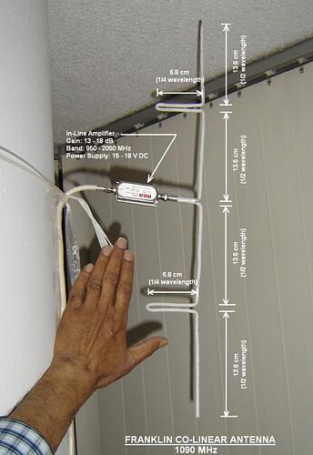
I have built this “folded upon itself” haif wave section, also known as “phasing stub” or “phasing hairpin”. It is called “Franklin Collinear” after its inventor.

One of my 1090 Mhz antennas built in 2013:


https://farm8.staticflickr.com/7749/18197545158_c8c550d241_o.png

https://farm9.staticflickr.com/8799/17764783483_449aa1b228_o.png

1 Like

.
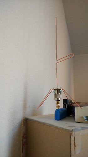
There is another design using phasing stub/hairpin. I have named it “Franklin-Spider”.

Franklin-Spider built by caius

Franklin-Spider built by Xforce

You mean I didn’t invent it? :slight_smile:

Thanks. I thought of the Franklin hairpin spider myself. I also found another discussion about this design here.
forum.flightradar24.com/printthr … 40&page=43

Search for “large size” to get to the part of the thread discussing it.

So how were your results from these designs? The discussion of gap size and impedance matching have me thinking I need to construct it more carefully than I’d originally conceived. How does the impedance vary with hairpin gap size? What impedance should I shoot for to connect to the pro stick?

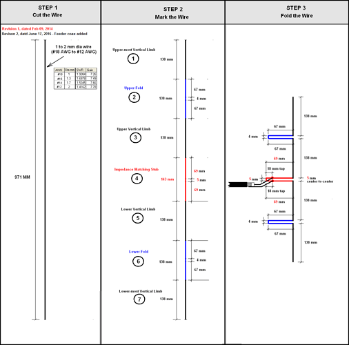
DIAGRAM 1/2 - FRANKLIN DIPOLE
(The diagram is too wide. Please scroll right to see the complete diagram)

Results: Most builders reported moderate to good. Wire bending skill counts.

Notes:
(1) Coax connection point (shown in Step 3 of diagram as “tap” on middle hairpin) to be adjusted by trial and error. Performance greatly dependent on proper adjustment.

(2) The gap between wires of Phasing Stub (upper & lower, shown blue in the diagram) is not critical. It is shown 4mm, but can be 3mm to 7mm.

(3) The gap between wires of Impedance Matching Stub (middle one, shown red in the diagram) is shown 5mm. For gap of this stub “smaller the better” applies. From practical considerations the gap cannot be reduced beyond 3mm. If even 5mm is too tight, go for 6mm, but not more, as bigger gap of Impedance Matching stub dont bring good impedance match/SWR.

(4) Hairpins (stubs) need to be tied by spacers or ties, otherwise by weight, they open up and change their shape from U to V.

SCROLL RIGHT TO SEE FULL DIAGRAM >>>>>>>>>>>


SCROLL RIGHT TO SEE FULL DIAGRAM >>>>>>>>>>>

DIAGRAM 2/2 - FRANKLIN-SPIDER

Results: Mixed results. Some builders reported better than, and some reported less than the standard 1/4 wavelength Spider.

Note: Gap between parallel wires of phasing hairpin (stub) can be from 4mm to 7mm

EDIT: Revised Diagram 1 (Franklin Dipole): Feeder Coax added

Dumb question - why 4 segments (aka limbs in your diagram)? Would making 6 or 8 improve reception?

“(1) Coax connection point (shown in Step 3 of diagram as “tap” on middle hairpin) to be adjusted by trial and error.”

I’ve seen a similar design where this portion was longer. Instead of a 1/4 wave length each direction, it’s 1/2 wave, with the coax attached at 1/4 wave. Additionally, there is a balun in some of the designs. The example on this page doesn’t seem to have one, though.

iz0ups.jimdo.com/antenne/hf-raccolta-antenne/

Increasing segments results in increased gains with a diminishing return: the more segments you have the less benefit there is to add more. Increasing segments also narrows the bandwidth, which shouldn’t be a problem for us, assuming it’s properly tuned. The more segments, the more precisely you have to measure. Finally, the more segments, the flatter the pattern. Too many segments and you may not be able to pick up signals originating high up. This is easily demonstrated by drawing incoming wave trains coming at different angles. The signal will start being compromised when the wave train at one end is out of phase with respect to the wave train at the bottom. Let’s assume 1/2 wavelength is as much out-of-phase as we want to tolerate. Then using simple trigonometry, we can calculate the elevation angle where the signal gets compromised. sin(angle) = a/h, where a is 1/2 wavelength, or the amount of out-of-phase we want to tolerate, and h is the height of the antenna (2 wavelengths for the 4 segment one). So we have arcsin(0.25) which is about 14 degrees. If we use an 8 segment antenna instead, we get an angle of 7 degrees instead (signals from planes higher than 7 degrees above horizontal will be reduced).

Perhaps more relevant is the angle at which the full signal is canceled out. We simply use a=1 instead. For a 4 segment antenna, the angle would be 30 degrees. For an 8 segment antenna, it would be 14 degrees. Do you have planes passing over higher than these angles? Then you probably don’t want that many segments.

Higher angles generally mean closer planes, so this effect is probably desirable to some extent so the signal is not too strong for close planes.

In nutshell, yes increasing number of elements will improve reception, but not as much as generally imagined.

ExCalbr’s explanation is exhaustive, and there is nothing more I can add to it.

Since our brains comprehend an explanation more easily if it is quantitative & graphic, I would like to present ExCalbr’s descriptive explanation in that way:

(1) GAIN:
Normal expectation is that doubling the number of elements (i.e. from 4 to 8 ) should double the gain, and quadrupling the number of elements (i.e. from 4 to 16) should quadruple the gain.

In reality, each doubling of number of elements only increases gain by 3 dBi. Hence this is what happens:

Number of elements = 4 ; Gain = 7.5 dBi
Number of elements = 4 x 2 = 8 ; Gain = 7.5 + 3 =10.5 dBi (expected was 2 x 7.5 = 15 dBi)
Number of elements = 4 x 4 = 16 ; Gain = 7.5 + 3 + 3 =13.5 dBi (expected was 4 x 7.5 = 30 dBi)

… this is “Law of diminishing return” mentioned by EXCalbr :frowning:

(2) RADIATION PATTERN
The radiation pattern shape is like symbol for infinity ∞. Increasing number of elements flattens this shape, resulting in better response for signal originating far away planes (seen by antenna at horizon or very shallow angle), compared to nearby planes (seen by antenna at an elevation of 30 degrees or more). Since signals from far away planes are weak and nearby planes strong, this perfectly suits our requirement.

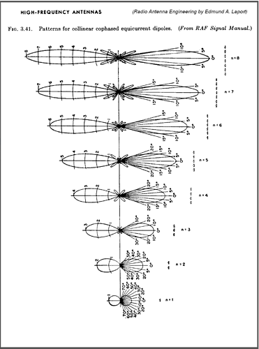
Just to make the ExCalbr’s and my explanation easier to understand, I am attaching two images below. A picture is worth 1000 words :slight_smile:

Image 1/2
Comparison of Radiation Patterns of Isotropic, Half-Wave Dipole, 4-element Franklin & 8-element Franklin Antennas

Image 2/2
Source: Radio Antenna Engineering by Edmund A. Laport, former Chief Engineer RCA
(originally from Royal Air Force Signals Manual)

Thanks for the pictures. It also becomes clear that the more elements you have, the more precisely the whole rig must be mounted. Any divergence from perfectly vertical (or, actually, perpendicular to the plane of activity you are targeting) has a greater impact with more segments.

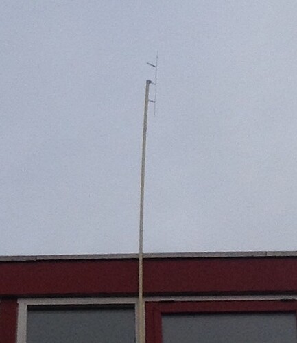
Examples of outdoor Installation of Franklin Antenna

Picture 1 of 3
Built by lutorm.
2-meter J-Pole + 4-Element 1090 Mhz Franklin (at right, on edge of horizontal arm).

Picture 2 of 3
6-Element 1090 Mhz Franklin Built by Karains

Picture 3 of 3
4-Element 1090 Mhz Franklin built by bramj

I see decent results from mine in conjunction with an lna4all. Quite a bit better than a basic 1/4 wave ground plane, and marginally better than a commercially made Sandpiper (same as Radar-Rama design, though that has previously been mounted outside for some time and I suspect it needs cleaning up internally a bit). I see a peak of just over 1800 msgs/sec, 290 aircraft in view and max range about 240 nautical miles. It’s mounted in the loft space and I’m in North East London.

Lots of conflicting values for determining the length of the segments - guess I need to wander into “velocity” or some such magic.

My first Franklin collinear is a single piece of 14 gauge bare copper wire. The vertical segments are 114mm, the ‘loops’ are 68+10+68mm. I have 1100mm (1.1m) of 75ohm coax soldered 30mm from the U-turn in the middle ‘loop’. It currently is my best performing antenna.

Then I saw this thread and decided to try again to get a better one - nope. Here’s what I did - maybe you folks can help me understand what went bad. I’ve use 2 pieces of 12 gauge copper wire (household wiring - left the insulation on for most of the length). Verticals are 138mm, loops are 68mm folded (so about 4mm between - insulation prevents a tighter fold). The center loop is a full 70mm with the tap at around 20mm from the end. Now the two sides are actually two different pieces of wire that I’ve soldered together at the center of the central loop/tap. I have twisted on at the tap point some CATVR(?) left over coax (about 1.2m). It gets only about 1/2 the positions that the others do.


I then built a cantenna. Lost some blood scouring the inside to get a good electrical contact between the shielding of the (2m RG6U)) coax and the can. I have left the insulation on the center conductor. The antenna is 68mm and the can is 68mm. It is working quite well - although not quite as good as my first collinear.

Picture 3 of 3
4-Element 1090 Mhz Franklin built by bramj

I stop using this antenna , to much performance loss when its rains.
Now i’am using FlightAware Pro Stick , filter and antenna…

http://bram-inge.demon.nl/show/flight-pro-2.png

http://bram-inge.demon.nl/show/flight-pro.png

My best antenna for a long time was a 6 element Franklin. It took me several attempts to make one that worked well. Once I’d got one that worked, I folded the stubs around a piece of tube so the antenna could be slipped into some 22mm tube to give it some protection from rain. I never finished it as I got distracted with CoCos :unamused:

You did, or did not account for velocity factor? The sizes look different, so it seems like you did. But did you do it correctly? The velocity factor will vary according to the material the insulation is made from. With no insulation, the velocity factor is near unity. Probably about 0.96 or so for bare copper. Using 1 is probably close enough. The insulated one will be slower, so the segments should be closer together. It looks like they’re farther apart. Did you do the reciprocal of what you should have?

Doing some quick calculations, it looks like the lengths should be 132mm and 66mm for bare copper, 91mm and 45mm for solid polyethylene coated copper, 96mm and 48mm for PTFE-coated copper, 110mm and 55mm for foam polyethylene coated copper.

Actually, what I would do is to mark the wire before bending it - easier to measure that way.

Doing some quick calculations, it looks like the lengths should be 132mm and 66mm for bare copper, 91mm and 45mm for solid polyethylene coated copper, 96mm and 48mm for PTFE-coated copper, 110mm and 55mm for foam polyethylene coated copper.

Are there sites / calculators that can aid in estimating velocity?

I actually didn’t realize/think about velocity. I just saw one post that had one set of measurements and made the first one (bare wire) and then based on this thread made the second one - without thinking about (much less understanding) how the insulation would affect velocity.

So, if the insulation in effect requires shorter lengths, then my best bet (easiest hack for now) would be to strip the insulation off my latest / largest Franklin and retest?

@ehud42 - I found that accuracy is king. A couple of mm here and there made the antenna useless.

The velocity factor will vary according to the material the insulation is made from.

Ok, so now I’m spinning in analysis paralysis :slight_smile:

What about the plastic/fibre glass tube folks are slipping their CoCos into? Does that further impact the velocity factor and require different lengths?

(Sorry - just trying to get a better handle on this concept)

That is a question I have, too. I assume so, if the dimensions of the containers are small enough, e.g., less than 1/4 wave in diameter, maybe.

If you search for velocity factor table you will find some hits where the table includes insulation with an air space. I don’t have one in front of me at the moment, but I recall that the velocity factor was significantly closer to 1 with an air space than without. The velocity factor also depends on the thickness of the insulation. Ideally, your setup should be site tuned. That requires equipment that I’ve never used, so I don’t know what all is involved.