Hi Martin,
Any chance of a picture/drawing for those who have no imagination ![]()
![]()

Hi Martin,
Any chance of a picture/drawing for those who have no imagination ![]()
![]()
**You mean this way?
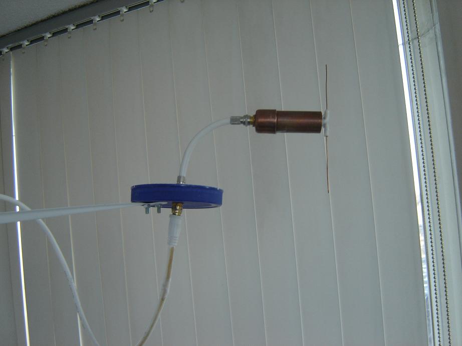
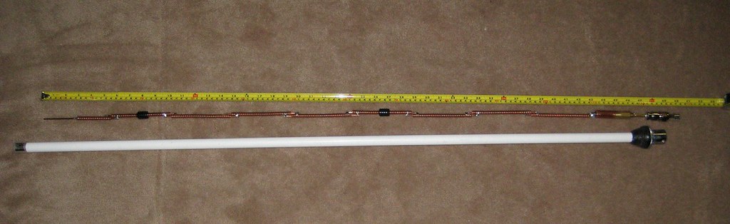
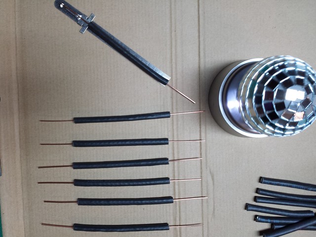
Six months ago I made a Bazooka Balun for my 1/4 Dipole. I will use the same for my CoCo, and see what happens.
image 1 of 3 - parts
image 2 of 3 - assembled
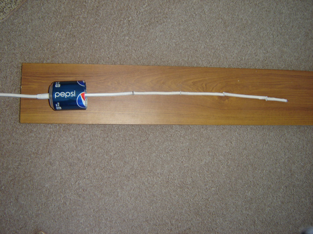
image 3 of 3 - on my Antenna Test Launchpad ![]()
Hi Ab Cd,
In this instance the top end of the 1/4 cylinder should be shorted to the screen rather than the bottom.
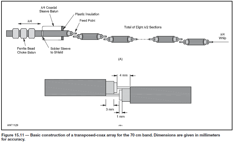
Like the bottom end of this commercial 3.5GHz coax collinear.
Here’s another image that shows the same method.
http://idkf.bogor.net/idkf/amateur-radio/wlan-24ghz/antenna/collinear/figs7.jpg
Here’s the full weblink
http://idkf.bogor.net/idkf/amateur-radio/wlan-24ghz/antenna/collinear/wa6svt.html
Regards,
Martin - G8JNJ
Hi Martin!
Thanks for the information about orientation of the sleeve.
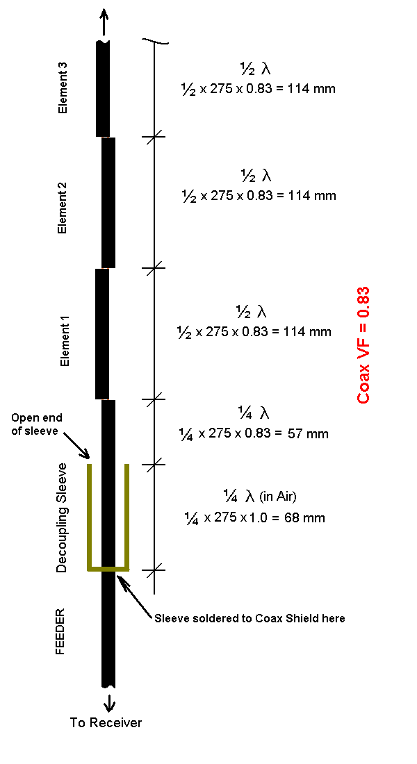
Now I am confused… orientation of sleeve the way I have shown is also in large circulation on web. Here is a drawing from ARRL Antenna Hand Book, which also shows the same orientation as I have shown… which one to believe? or maybe these two opposite orientations serve different purposes? ![]()
![]()
![]()
Hi AbCd,
Take a look at the top section ![]()
It’s a 1/4 wave in which case the sleeve balun is the other way around.
Draw out where the current nodes or voltage peaks will be along the antenna, it should then make sense.
Personally I favour the 1/2 wave commercial version. The radiating elements are effectively connected in parallel with each other by 1/2 wave sections of transmission line in both versions. However the 1/4 wave top section version places a low impedance across the feed point, the shorted 1/4 wave with additional 1/4 wave wire end top section places a much higher impedance across the feed point.
Which works better ?
I’m not sure but for a few sections the 1/4 wave top may give a better match, for a large number of sections the shorted 1/4 wave and 1/4 wave wire may be better.
Regards,
Martin - G8JNJ
Hi Martin!
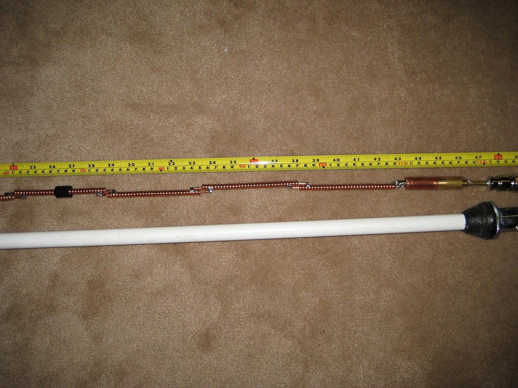
Below are photos of a CoCo made of LDF1-50 coax, having element at top “1/4 wave shorted coax + 1/4 wave whip”, like Mike Collis WA6SVT design, but it’s sleeve is like ARRL design:
(1) The open end of sleeve is towards antenna.
(2) The piece of coax between first element and sleeve is of negligible length, and not 1/4 wavelength
Now see the comments posted by Peter Fairlie, the maker of this CoCo (his nick name in FR24 forum is “1090 MHz”):
[quote=“1090 MHz”]I just finished building the collinear out of LDF1-50. It’s an 8 and a half element antenna with a shorted top whip. I like the idea of the DC short in the design as it will prevent static buildup on the center conductor however it’s still resonant at 1090 MHz… the magic of antennas!
The first collinear I built was out of RG59 and it didn’t work very well… its first test was in my basement which is below ground. It picked-up nothing down there which I now know as a sign it wasn’t going to work very well at all.
Now the new LDF1-50 collinear was carefully constructed and even a sleeve balun in the base added & cut to a 1/4 wave. I just tested the new LDF1-50 collinear antenna in my basement, it’s 3AM Monday morning and the quietest time of the week for air traffic… guess what? It was picking up aircraft … quite a few of them down in the basement… the antenna seems to be very sensitive! If it doesn’t rain tomorrow I will be up the tower and installing it. I now have N connectors for the LDF1-50. Here are some photos… I’ll take some tomorrow of the new antenna installation and cabling…
ads-b.ca/LDF1-50/super-antenna/
[/quote]
.
Hi AbCd,
It’s a good attempt, but it still doesn’t look quite right to me ![]()
As I think we are both aware by now, having a resonant antenna with a good match doesn’t necessarily mean that it provides the gain that the design parameters suggest. In this case there’s a good chance it is providing some gain, but I think the bottom section lets it down, as it is placing a low impedance point at the base and then feeding the first 1/2 wave section at a high impedance point directly above it.
By reversing the sleeve and connecting it 1/4 wave down the first section, the sleeve and coax section above the sleeve become the first 1/2 wave radiating section.
Both methods will work, but I suspect the second will provide slightly more gain and a better pattern, however I’d be happy to be proven wrong, as I would learn something new in the process.
Here’s another link which may help to explain the operation of sleeve balun in more detail.
http://www.w8ji.com/sleeve_baluns.htm
Sorry I’m a bit pushed for spare time at the moment, but can I suggest that you either draw an outline of the antenna and add the current and voltage nodes, or better still, if you could add the sleeve balun to your 4NEC2 model in both configurations, then we could all see what’s happening.
Regards,
Martin - G8JNJ
Hi Martin.
From link above:
" The following construction guidelines apply:
The cable should have a good low-loss jacket or a very large air or low loss dielectric gap between the shield and the sleeve. Since energy is normally confined to the inside of a coaxial cable manufacturers are not concerned about jacket losses. They use outer materials with long life, not low RF loss. It is advisable to use a filler material with a high volume of air to maximize sleeve impedance and minimize sleeve losses."
I use some layers of the thin transparent PE thermoplastic tube heatsetting over outer material of coax to reduce losses, then place sleeve (cupper shield cutted from coax with greater diameter) about 45-46 мм long (calculated Er~2.2), then soldering and waterproof covering with another piece of thermoplastic tube.
Best regards,
Serge
In June 2014, I added a wide-diameter sleeve balun to my CoCo. I did not notice any improvement.
May be it was due to reversed orientation of the sleeve.
May be it was due to random distance of sleeve from end of first element of CoCo.
The top element of my Coco was 1/4 wavelength coax, shorted at top (no whip)
Click HERE and HERE.
Photo: June 2014
What happened to this thread - is no one experimenting with collinear antennas any more?
I am recently starting with ADS-B and a ‘simple’ quarter wave ground plane antenna connected by short coax to a R-Pi (currently in the attic and accessed by ethernet to avoid long/lossy coax).
I now want a ‘better’ antenna with some ‘gain’ toward the horizon and the CoCo could be a clean solution.
I’m aware of the difficulties that seem to dog this antenna and the abundance of incorrect material on the t’interweb.
I am building a CoCo with shorted 1/4 wave top section and tube balun at the feedpoint. I also have the possibility to add some ferrite rings at 1/2 wave below the balun if further choking is required (ferrites gleaned from a defunct wifi access point).
If it is at all successful, I’ll post on here.
Incidentally, my 820T2 dongle is modified with several of the mods outlined by Martin - G8JNJ ![]()
Nigel - G4ZAL
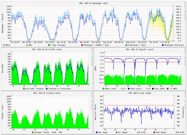
I’ll let my stats speak for my results using a home built 8 segment COCO:
flightaware.com/adsb/stats/user/ … stats-5696
My recent couple weeks stats have been reduced due to issues with my internet provider. You will see a nice bump up over the weekend from my finding a workaround to “their” problem. (MAC cloned my router to get a different IP address)
Cheers!
LitterBug
@LitterBug
Your stats are great. Congratulations, you are high up in ranking (within top 100).
As far as antenna performance is concerned, stats dont give a real picture as stats depend not only on antenna, but also on location (which determins traffic and maximum range) and hardware like coax, amplifier & filter. The antenna can be judged properly only if its stats are compared with another benchmark antenna at same location, and with same hardware like coax, amplifier & filter etc. A 1/4 wavelength groundplane antenna like Spider or Cantenna, serve as a good benchmark antenna because of their reliable reproduceability in DIY enviroment.
If it is ok with you, it will be nice if you post some photos and/or drawings of your Coco.
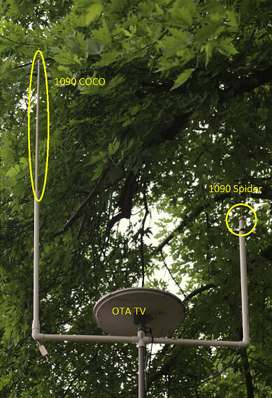
I have done side by side comparisons of several simple antennas including discone, spider, dipole, and the antennas that came with my dongles. So far from my results at my location, none of them have been able to match the results I get with the COCO. I lent one of my COCO antennas out to someone local who compared it to the new FA antenna. He said his results were better with my COCO under the same conditions. (I could not convince him to let me borrow it and test it at my location) My setup is not ideal as there are trees directly around my antenna mast. I have masts made of PVC that I use as slip joints for easy swapping of antennas with seperate feed lines. Makes it easy to test side by side as well as replace/swap things when stuff is not working right. I use Paladin 20db and/or Perfect Vision 30db amps. With the COCO, I can set the dongle gain down very low without loosing much range or flights. (less heat too) Results are almost identical between the Paladin and PV amps despite the difference in amplification. With a spider, I never got closer than 75% of the stats from my COCO and had best results with the 30db PV amp and highest gain setting on the dongle.
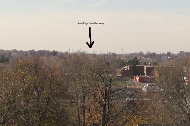
Here is a quick shot of my rooftop setup when I was testing a COCO vs a spider:
Ideally I would like to feed from this location on the other side of town:
Cheers!
LitterBug
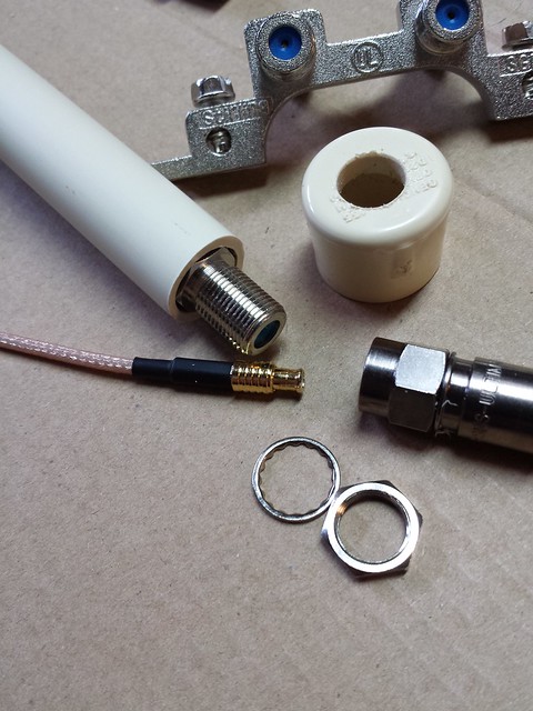
Construction of my COCO:
The center conductor of the cable I use is not bonded to the white insulator. This make it very easy to push the center conductor out of the way, make a clean cut, and then push the conductor back through. All segments are slip fitted. Eight segments total and open at top. (not shorted, no resistor) This is all attached to a short stub with a male F-connector screwed into a female-female F-connector. Depending on mounting location, I may put a cap on the end, or leave it open. All connectors are waterproof. I now also use dielectric grease on all threads after having a seepage issue during the rainy season.
Antenna → short feed → amp → 20’ feed line → Ground block → 10’ feed line → Direct TV power inserter → 3’ feed → T2 dongle
Very closely matched segment lengths rough measured first with a ruler, final check with micrometer.
Slide whole thing into PVC jacket and attach end cap if desired:
@Litterbug Great photos
I made my 8 and 12 element CoCos the same as you. It took me about 10 - 15 attempts to get it right.
Here are my stats https://uk.flightaware.com/adsb/stats/user/triggers#stats-12366
I have a similar setup at my brother’s house https://uk.flightaware.com/adsb/stats/user/triggers#stats-15612
I did make it into the top 20 last year but more people have built much better antennas and FA have changed the way they produce the stats.
My next CoCo will be some 6mm copper tube as the outer with the core and insulation from my coax pushed into it. I’m having trouble soldering the bits together but will get there eventually ![]() I will, of course, report back here when (if) I succeed.
I will, of course, report back here when (if) I succeed.
The CoCo after that one will be an attempt to make an air insulated CoCo. Should be fun 8)
Nice Triggers!
My COCO’s worked right out of the box. The sliding center conductor really made it easy. I started on copper COCOs last winter and have all the bits cut. I’ll post my results as well once I complete them. Was intending on building an open air-inline and a typical open air staggered design.
Cheers!
LitterBug
This is very encouraging.
g to know that you coco are working great.
It will be beneficial for all who have failed to build a successful one, if you two can post the key construction parameters, i.e.
Type of coax used (RG59, RG6, LDF1-50 etc)
VF of coax & length of elements
Any construction tips.
I am also amongst the large group of failed coco makers, and very much interested in a reproducible design. However instead of throwing in trash bin my last failed coco, I have added impedance matching to enhance its poor response, but I still feel making a good coco in first place is a much better solution.
Good to see some successful CoCo antenna builders with decent results.
Here is my initial data…
uk.flightaware.com/adsb/stats/user/Devonian
Simple homebrewed 1/4 wave ground plane indoors in the attic with no pre-amp etc, just antenna into R-Pi via short coax - max 1 metre.
I’m not in a real decent location to grab lots of flight data, unlike some of you guys.
Started some work on a CoCo this evening, will post some pics when I can.
Regds,
Nigel.
Hi Nigel, have you plotted your theoretical horizon(s) with Heywhatsthat? There is a thread somewhere on here with instructions. One can spend hours chasing the last mile only to find there’s a hill blocking everything below 20,000 ft. ![]()
I have the Chilterns to my East and they block my view to the ground at Heathrow.
Regards,
Dave
Hi Dave,
I haven’t seen that about horizons, but I pretty much know my best directions for ‘take off’ as I am also an Amateur Radio operator and have reasonably clear line of sight from West through North to East, but to the South I have hills right behind me and can’t work Exeter just 15 miles South of me on VHF.
I’m not after the last drop, but want the best I can achieve without splashing on expensive commercial antennas.
When I’m satisfied with the results indoors, I will install it on the gable end of my house so it will have minimal coax run as I can put the R-Pi in the attic, close to the gable end.
The Pi is online here…
nthead.co.uk/dump1090/gmap.html
A friend has just offered me some Andrews Heliax LDF1-50 so my current CoCo build may stop until I get my grubby paws on some decent coax ![]()
Cheers,
Nigel.