TomMuc has identified the filters which take out unwanted frequencies the best.
However, don’t we also need to collect parameters like aircraft reported, coverage, positions reported by distance etc for each of the filters.
I have a homemade coax stub filter which removes all the frequencies in the 920 - 960Mhz but also removes most of the 1090Mhz frequency too!
I haven’t been following all the threads regarding filters so please forgive me if this has already been done.
@triggers this is what i did too but what is not really easy to display the results. you can’t measure this with a single setup over long time as traffic, routes, weather, atmospheric things etc. change over time. range plots like vrs does are worth nothing especially over long time and/or mlat using. ads-b is not like astronomy or ham radio about distance records - it’s again worth nothing to sometimes pick up single or very few or bogus signals from far away. ads-b is about to pick up maximum numbers of messages over a maximum area.
there are two ways that work - to see what results in live ads-b mode different filters and lnas give. the first is very complex - using the same antenna, a splitter and behind that the different filter/lna/dongle/raspi setups. the problem here is to just exactly compensate the splitter loss and channel differences. then you have to find two dongles, cables with exact same behavior. and even then one dongle could interact with the other. i did all this for some filter/lna combinations - but it is really extremely time-consuming and still has lot room for wrong results.
what gives me by far the best results and is very fast. just use one receiver and antenna on different times of the day. run one setup for about 1-2 minutes and then another. doing this like a ko-system and repeatedly you get a very good overview what works best at your site. some of the results cannot be generalized but some can absolutely.
that said - my results in real ads-b numbers exactly match the seen results in the above band-scans. what can be generalized is:
it’s always the second best idea to combine two filters
an ideal filter has very low insertion loss and huge attenuation over a large frequency-band
the nearer noise-frequeny is to ads-b the bigger the challenge for filter/receiver
a filter in front of lna is better than behind but must have very very low insertion loss
=> from all filters i ever tested the jetvision 3-pole has by far the best overall performance
=> the by far best bang for the buck delivers the uputronics saw-filter/lna combo
=> the 10$ generic chinese dongle is an unbelievable good sdr
@triggers
please do not overrate this! but here are two vrs-range plots both over about 1-2 weeks not simultaneously. the first is uputronics saw/lna and the second is jetvision 3-pole filter/lna. as i often mentioned - this is something you should not really compare in detail - but the trend is obvious …
another parameter one have to keep in mind is that different filters have different passband (1090mhz) attenuation. so you maybe have to adapt the gain setting of dongle too. there are some scripts around here in the forum that automize this - but i’m not a friend of this method and in my testings often showed wrong results.
the easiest way to see what gain works best is to watch skyview for about 1-2 minutes → then alter the gain setting and again look on skyview for message-rate, aircraft numbers with/without position, aircraft pattern on map, highest aircraft distances and age of messages.
to change the gain setting in dump1090-mutability simply use the two below lines:
sudo sed -i -e 's/GAIN=".*"/GAIN="48.0"/g' /etc/default/dump1090-mutability
sudo /etc/init.d/dump1090-mutability force-reload
A quarter wave stub shouldn’t remove “most of the 1090Mhz frequency too”. The insertion loss in the pass-band should be quite low.
What type of coax did you use to make the filter?
and exactly how long did you make the stub?
btw. here are two pictures from my tinker-lab. first shows what happens if one is too dumb to desolder a saw filter - the second shows inside of the minicircuits 2-way splitter zapd-2dc+
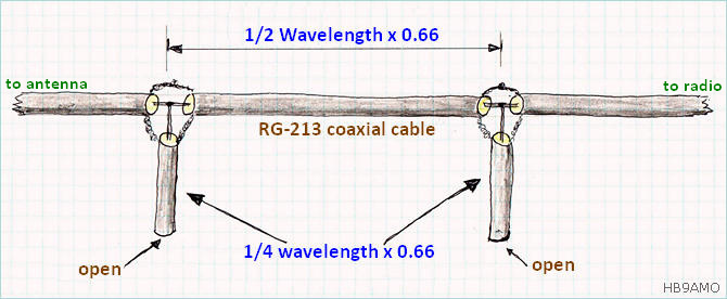
I used unknown manufacturer coax but the VF is 0.66. I used a “T” in the feedline. The distance from the centre of the “T” to the end of the open ended stub is 53mm. I started with a 60mm stub and gradually chopped bits off & re-ran rtl_power.
This is my raw data
However, when I insert the stub the messages dropped from 880/sec to 710/sec and the plane count from 142 to 106. I also lost some of the distant planes too. Gain is 49.6
Antenna is a homebrew 8 element Coax Collinear located in the loft with approx 6m of coax with Flightaware Pro (Orange) dongle This is my test setup.
That could be your problem: An open 1/4 λ stub is a band-stop or notch filter which would certainly explain your poor performance (A shorted 1/4 λ stub operates as a band-pass filter)
If you need to avoid a DC short (you are using a bias-T etc.) then you need to use a 1/2 λ open stub to give you a band-pass filter.
There is so much variation in coax spec/performance that you may be setting yourself up for problems by guessing.
A Vf of 0.66 suggests you are using RG59 rather than RG6 which typically has a Vf around 0.82 (Belden does list an RG6 with Vf of 0.66 out of the 61 RG6 variants it offers).
If your coax does have a Vf of 0.66, than λ/4 should be around 45mm.
One thing to be careful of when using RG59 with type-F connectors is that the centre conductor is much slimmer than that of RG6, so may not make reliable contact particularly if the connector has been previously used with RG6.
@geckoVN - many thanks for your comments.
I know very little about filters etc. My thinking went along the lines of
I need to get rid of the frequencies at 920 - 960Mhz. 1/4 λ of 940Mhz is 79.8mm. I know the VF of my coax is 0.66 so stub length should be 53mm
I take your point about the diameter of the centre conductor. I’ll measure mine this afternoon.
Ah! I’d misunderstood what you were trying to achieve (or rather, how you are trying to achieve it).
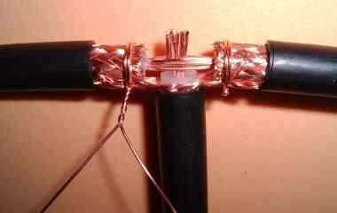
I looked at Volker’s T-joint. It’s very neat, but is being used on a 146MHz transmitter to remove the third harmonic (70cm amateur band).
Replicating it precisely to be suitable for 1090 MHz will have it’s own set of problems. Continuing with a three-way adapter is certainly easier and probably more reliable.


